A device for flattening the end face of a cell

A cell and end face technology

Active Publication Date: 2022-02-01
WUHAN YIFI LASER EQUIP CO LTD
View PDF10 Cites 0 Cited by
  • Summary
  • Abstract
  • Description
  • Claims
  • Application Information

AI Technical Summary

Problems solved by technology

[0007] The invention provides a flattening device for the end face of the electric core to solve the technical problems of complex shaping process, high cost and poor shaping effect of the existing electric core end face

Method used


Image

  • A device for flattening the end face of a cell
  • A device for flattening the end face of a cell
  • A device for flattening the end face of a cell

Examples


Embodiment Construction

[0028] The specific implementation manners of the present invention will be further described in detail below in conjunction with the accompanying drawings and embodiments. The following examples are used to illustrate the present invention, but are not intended to limit the scope of the present invention.

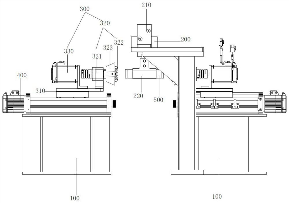
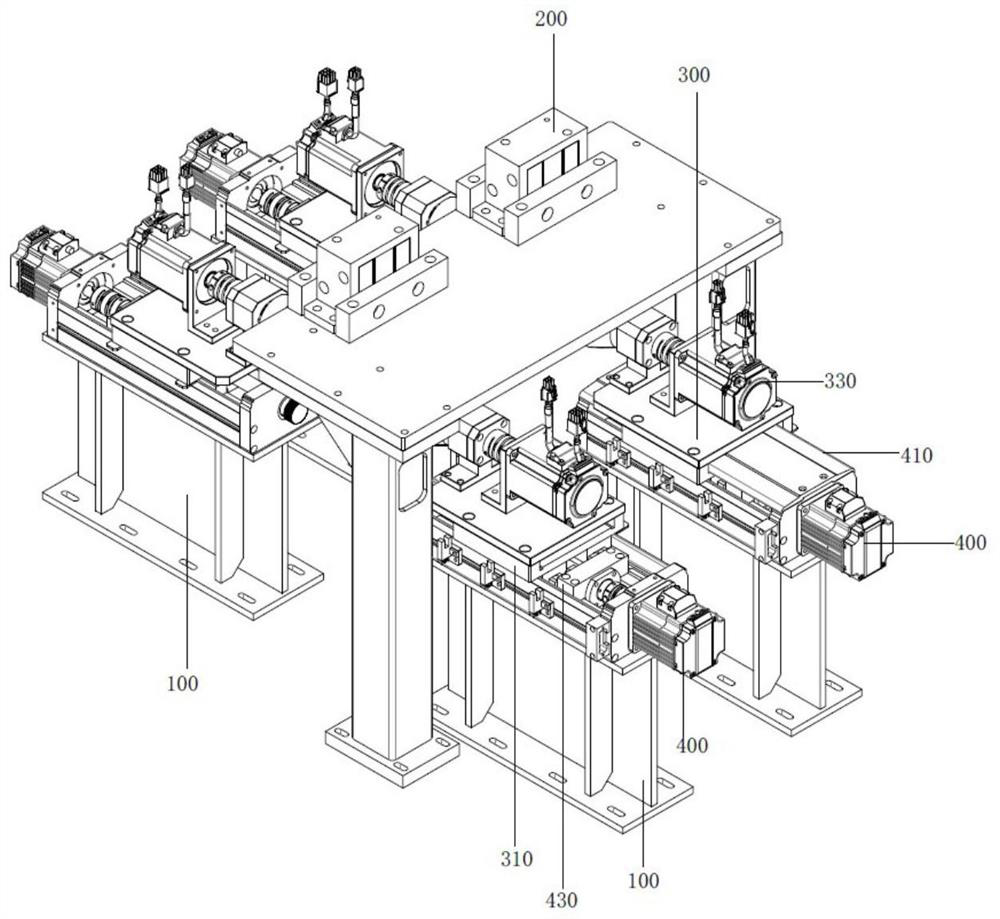
[0029] see figure 1 , and combined with figure 2 As shown, a cell end face kneading device of the present invention includes a frame 100 , a cell clamping device 200 and a kneading device 300 .

[0030] The cell clamping device 200 is used for clamping the cell, and the flattening device 300 is used for shaping the end face of the cell 500 , and the frame 100 is used for installing and supporting the cell clamping device 200 and the flattening device 300 .

[0031] Wherein, the cell clamping device 200 of the present invention is arranged opposite to the kneading and flattening device 300, and the cell clamping device 200 is installed on the frame 100 through a rotary d...


PUM


Abstract

The invention provides a device for kneading and flattening the end face of a battery cell, which includes a frame, a battery cell clamping device and a kneading and flattening device. On the frame, the kneading and flattening device is slidably installed on the frame, and can move back and forth relative to the kneading and flattening device. In the present invention, the cell clamping device and the kneading device are arranged on the frame, and the cell clamping device is used to realize the fixed clamping of the cell, and the kneading device is used to realize the kneading and shaping of the end face of the cell; at the same time, In the present invention, the battery cell clamping device is installed on the frame through the slewing device, and the slewing device is used to drive the battery cell clamping device to rotate, so as to realize the automatic reversing of the battery cell, which can not only improve the processing efficiency, reduce labor intensity, but also avoid The clamping error caused by the secondary clamping is eliminated, resulting in differences in the shaping effects of the two end faces of the battery cell, which affects its processing quality.

Description

technical field [0001] The invention relates to the technical field of battery preparation, and more specifically, to a device for smoothing the end surface of a battery cell. Background technique [0002] The existing large-capacity cylindrical lithium-ion batteries mostly use full-tab positive and negative electrodes. At present, the existing battery generally adopts the positive and negative electrodes of the full tab type, that is, when the positive electrode slurry is coated on the positive electrode current collector (usually aluminum foil), a part of the area not coated with slurry is reserved on the edge of one end (positive aurora foil area). ), when coating the negative electrode slurry on the negative electrode current collector (usually copper foil), reserve a part of the area (negative aurora foil area) where the slurry is not coated on the edge of one end. After the positive electrode sheet, the negative electrode sheet and the diaphragm are wound to form the ...

Claims


Application Information

Patent Timeline
Patent Type & Authority Patents(China)
IPC IPC(8): H01M10/04H01M10/0587
CPCH01M10/0404H01M10/0587Y02E60/10Y02P70/50
Inventor 冉昌林王林周佳林张文华
Owner WUHAN YIFI LASER EQUIP CO LTD
Why Eureka
Try Eureka