
SAR image change detection method based on stack semi-supervised adaptive denoising auto-encoder

An image change detection and self-encoder technology, applied in the field of image processing, can solve the problems of large influence of learning samples, errors, and inaccurate detection results, etc.

Active Publication Date: 2017-11-24
XIDIAN UNIV
View PDF4 Cites 15 Cited by
  • Summary
  • Abstract
  • Description
  • Claims
  • Application Information

AI Technical Summary

Problems solved by technology

[0005] In 2012, Maoguo Gong and Yu Cao et al. published the article A Neighborhood-Based Ratio Approach for Change Detection in SAR Images in IEEE Geoscience and Remote Sensing Letters, Volume 9, Issue 2, Page 307-311, which proposed a neighborhood-based ratio operator (NR) , the NR operator adds the heterogeneity / homogeneity operator of the image, but when the noise distribution of the two SAR images before and after the change is inconsistent, the detection effect of this method is not accurate enough
Disadvantages of this method: First, the generation of initial change masks for optical images and SAR images will introduce large errors, and the learning samples with large errors will also have a greater impact on the results; second, SDAE uses an unsupervised method To extract features, so the extracted features have a certain degree of randomness, and the feature change analysis based on the mapping proposed by the author is completely dependent on the features extracted by SDAE, which will further introduce errors
[0008] To sum up, when the image noise distribution before and after the change is inconsistent, the above method is not good enough for edge detail detection, and the overall error rate of change detection is high

Method used


Image

  • SAR image change detection method based on stack semi-supervised adaptive denoising auto-encoder
  • SAR image change detection method based on stack semi-supervised adaptive denoising auto-encoder
  • SAR image change detection method based on stack semi-supervised adaptive denoising auto-encoder

Examples


Embodiment Construction

[0121] see figure 1 , the present invention provides a kind of SAR image change detection method based on unsupervised depth neural network, specifically comprises the following steps:

[0122] Step 1: Input phase 1 image I and phase 2 image J, I={I(u,v)|1≤u≤U,1≤v≤V}, J={J(u,v)|1 ≤u≤U,1≤v≤V}, where I(u,v) and J(u,v) are the gray values ​​of image I and image J at pixel (u,v) respectively, where u and v They are the row number and column number of the image respectively, the maximum row number is U, and the maximum column number is V.

[0123] Step 2: Compute the Multiscale Difference Guidance Map

[0124] (2a) For the 3×3 neighborhood of the pixel at the position (u,v) in the phase 1 image I and the phase 2 image J, calculate the mean value of the 9 pixel values ​​in the 3×3 neighborhood respectively, record for μ N3 (I(u,v)) and μ N3 (J(u,v)), and then calculate the 3×3 neighborhood mean difference value I at (u,v) according to the following formula S (u, v),

[0125] ...


PUM


Abstract

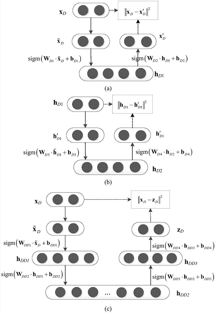
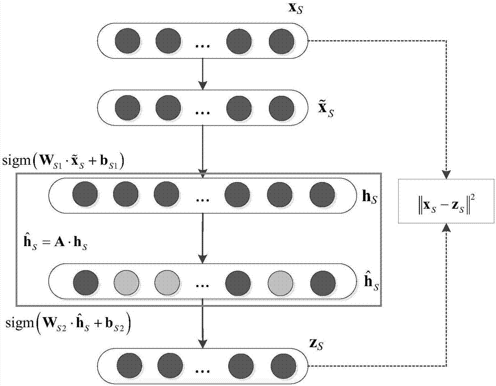
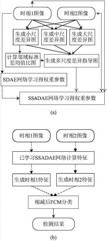
The invention discloses an SAR image change detection method based on a stack semi-supervised adaptive denoising auto-encoder, and aims at solving the problem that in an existing method, the precision of detection on coherent speckle noise points and change areas of many edges is low. The method comprises the steps that a multi-scale difference guide diagram is generated; a first time phase image is taken as the input to train an SDAE; the multi-scale difference guide diagram, the first time phase image and a second time phase image are taken as the input to train the SSADAE, and weights obtained in SDAE training are used in an SSADAE self-adaption error function; the feature vector of the first time phase image and the feature vector of the second time phase image are calculated by the SSADAE; and the feature vector of the first time phase image and the feature vector of the second time phase image are subtracted to obtain a difference vector, an FCM classification is conducted on the difference vector to obtain a change detection result diagram. According to the method, the multi-scale difference guide diagram is proposed firstly and can highlight the change areas in the difference diagram; and the SSADAE proposed later can improve the change detection accuracy by utilizing a small quantity of mark samples in the image.

Description

technical field [0001] The invention belongs to the technical field of image processing and relates to change detection of SAR images, in particular to a SAR image change detection method based on a stack semi-supervised self-adaptive denoising self-encoder. This method can be used in change detection of SAR images. Background technique [0002] Change detection is one of the key technologies in the field of remote sensing. It detects the changes in the gray value or local texture of images in different periods in the same imaging scene, and obtains the shape, position, quantity and other properties of the surface or objects of interest. change information. It has a wide range of applications in the fields of society, environment and military. [0003] In the multi-temporal SAR image change detection method, there are two main routes, one is post-classification comparison (Post Classification Comparison, PCC), and the other is post-comparison classification. The former me...

Claims


Application Information

Patent Timeline
IPC IPC(8): G06T7/254G06K9/62
CPCG06T7/254G06T2207/20081G06T2207/20084G06T2207/10044G06T2207/20224G06F18/23213
Inventor 王桂婷尉桦刘辰钟桦邓成李隐峰于昕伍振军
Owner XIDIAN UNIV
Learn More