
Chemical industry waste gas treatment equipment

A waste gas treatment equipment and chemical technology, applied in the direction of lighting and heating equipment, incinerators, chemical instruments and methods, etc., can solve the problems of large footprint, inconvenient installation and disassembly, waste of time, etc., to prevent pollution rings, eliminate The effect of odor

Inactive Publication Date: 2017-11-24
陈旭东
View PDF0 Cites 14 Cited by
  • Summary
  • Abstract
  • Description
  • Claims
  • Application Information

AI Technical Summary

Problems solved by technology

[0003] In the existing chemical waste gas treatment devices, generally one kind of equipment can only treat one type of waste gas or one type of waste gas, and then transport the waste gas to other waste gas treatment devices for secondary treatment. Such a treatment method is not only wasteful time, moreover, it occupies a large area, and it is very inconvenient to install and disassemble the equipment

Method used


Image

  • Chemical industry waste gas treatment equipment
  • Chemical industry waste gas treatment equipment
  • Chemical industry waste gas treatment equipment

Examples


Embodiment Construction

[0018] It should be noted that, in the case of no conflict, the embodiments of the present invention and the features in the embodiments can be combined with each other.

[0019] In describing the present invention, it should be understood that the terms "center", "longitudinal", "transverse", "upper", "lower", "front", "rear", "left", "right", " The orientations or positional relationships indicated by "vertical", "horizontal", "top", "bottom", "inner" and "outer" are based on the orientations or positional relationships shown in the drawings, and are only for the convenience of describing the present invention and Simplified descriptions, rather than indicating or implying that the device or element referred to must have a particular orientation, be constructed and operate in a particular orientation, and thus should not be construed as limiting the invention. In addition, the terms "first", "second", etc. are used for descriptive purposes only, and should not be understood ...


PUM


Abstract

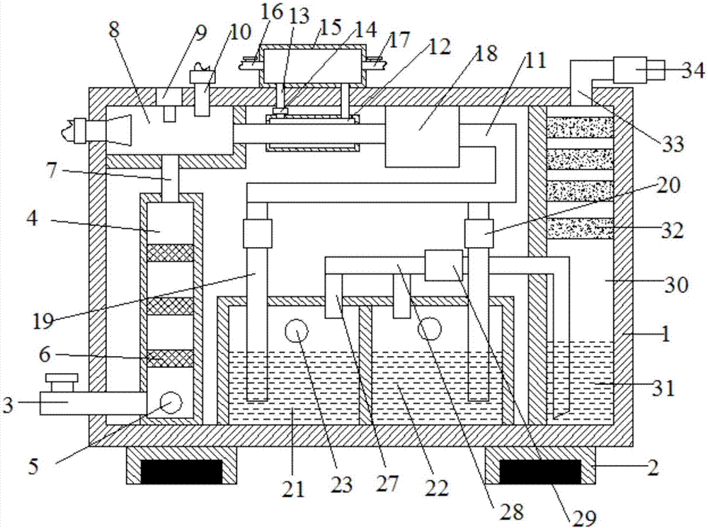
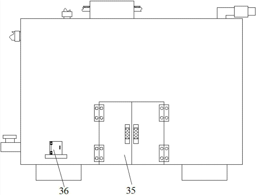
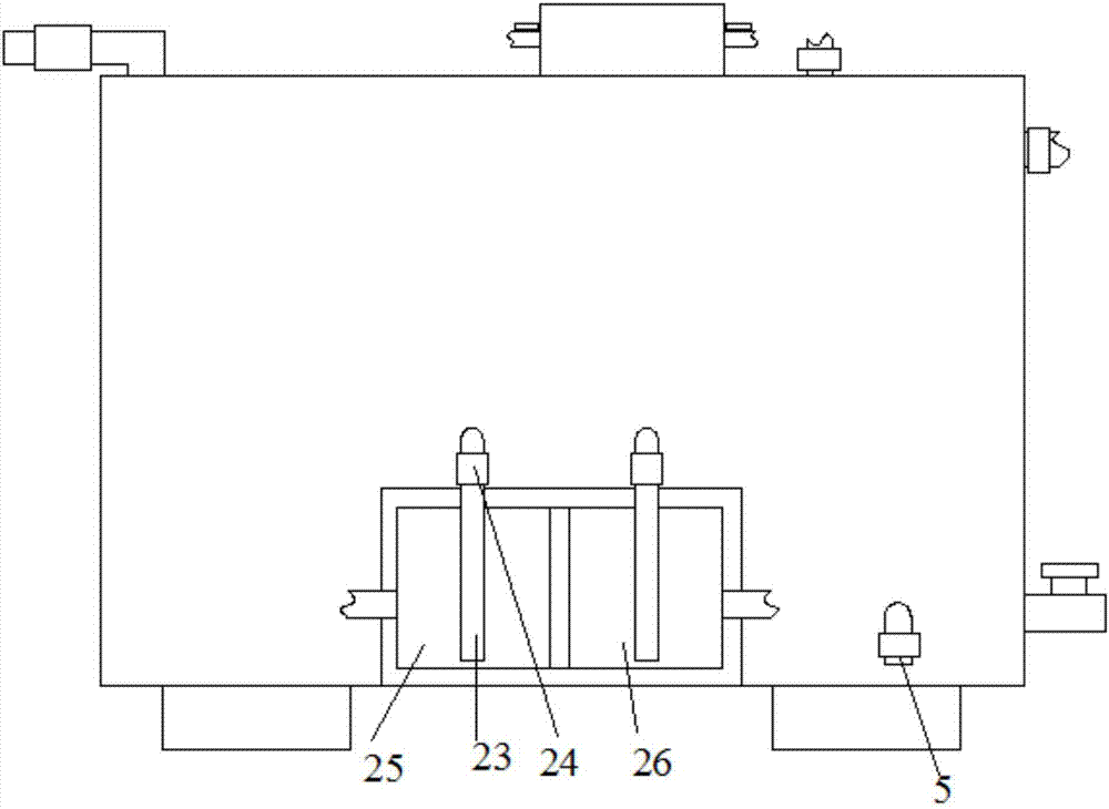
The invention discloses chemical industry waste gas treatment equipment, which comprises a box body, wherein the lower end of the left side of the box body is provided with a gas inlet pipe; a filtering cavity is arranged at the right side of the gas inlet pipe; a first connecting pipe is arranged at the upper side of the filtering cavity; a burning cavity is arranged at the upper side of the first connecting pipe; a second connecting pipe is arranged at the right side of the burning cavity; a condensation cavity is arranged at the left side of the upper end of the second connecting pipe; the left end and the right end of the upper side of the condensation cavity are provided with circulation pipes; a water storage cavity is arranged at the upper side of each circulation pipe; an acid alkaline detector is arranged at the right side of the condensation cavity; each of the left side and the right side of the lower end of the second connecting pipe is provided with a third connecting pipe; the lower sides of the third connecting pipes are respectively provided with an acid solution storage cavity and an alkaline solution storage cavity; the upper side of each of the acid solution storage cavity and the alkaline solution storage cavity is provided with a gas outlet pipe; the upper sides of the gas outlet pipes are connected with a fourth connecting pipe; the right side of the fourth connecting pipe is provided with a purification cavity; the upper side of the purification cavity is provided with an exhaust pipe. The chemical industry waste gas treatment equipment has the advantages that various kinds of harmful gases and suspended particles in waste gas can be effectively removed, so that the cleanness of exhausted gas is ensured.

Description

technical field [0001] The invention relates to an environmental protection equipment, in particular to a chemical waste gas treatment equipment. Background technique [0002] Chemical waste gas refers to the poisonous and harmful gas discharged from chemical plants in chemical production. Chemical waste gas often contains many types of pollutants, complex physical and chemical properties, and different toxicity, which seriously pollutes the environment and affects human health. The composition of chemical waste gas produced by different chemical production industries varies greatly. For example, the waste gas produced by the chlor-alkali industry mainly contains chlorine, hydrogen chloride, vinyl chloride, mercury, acetylene, etc., and the waste gas produced by the nitrogen fertilizer industry mainly contains nitrogen oxides, urea dust, carbon monoxide, ammonia, sulfur dioxide, methane, etc. [0003] In the existing chemical waste gas treatment devices, generally one kind...

Claims


Application Information

Patent Timeline
Patent Type & Authority Applications(China)
IPC IPC(8): B01D50/00B01D53/78F23G7/06F23J15/06B01D53/18B01D53/04
CPCB01D50/00B01D53/04B01D53/18B01D53/78B01D2253/102F23G7/06F23G2206/203F23J15/06Y02E20/12
Inventor 陈旭东
Owner 陈旭东
Learn More