Low-vibration motor with vibration isolation sleeve structure

A low-vibration and vibration-isolating technology, applied in electrical components, electromechanical devices, electric components, etc., can solve the problems of weak fixed rigidity of the stator core, poor equipment operation, damage to the motor, etc., achieving significant vibration reduction effect and high engineering application. Value, good thermal conductivity

Inactive Publication Date: 2017-11-21
HARBIN ENG UNIV
View PDF5 Cites 0 Cited by
  • Summary
  • Abstract
  • Description
  • Claims
  • Application Information

AI Technical Summary

Problems solved by technology

Usually, when the equipment is in use, a vibration isolator will be installed at the foot of the machine to reduce the vibration transmitted from the foot to the foundation. However, the vibration isolator is often made of elastic rubber and has a certain degree of elasticity. It is better to install it directly. Firm, the motor is prone to large shaking when it is disturbed by other external vibrations, resulting in poor operation of the equipment or even damage
[0004] At present, there is a scheme to isolate the stator core with a stator bracket to isolate vibration, but in this scheme, the stator is fixed with a bracket, and there are feet at the bottom of the bracket, which are fixed on the bottom of the motor frame by the feet. The fixed rigidity of the stator core is weak, and it is easy to shake in the machine base under the action of electromagnetic force, resulting in sweeping and damage to the motor
[0005] According to the relevant literature, there is only a bushing structure for the convenience of replacing the stator, but there is no public report on the modified motor that adds a vibration isolation sleeve structure to the motor body structure to reduce vibration transmission

Method used


Image

  • Low-vibration motor with vibration isolation sleeve structure
  • Low-vibration motor with vibration isolation sleeve structure
  • Low-vibration motor with vibration isolation sleeve structure

Examples


Embodiment Construction

[0023] Below in conjunction with accompanying drawing, the present invention is described in detail:

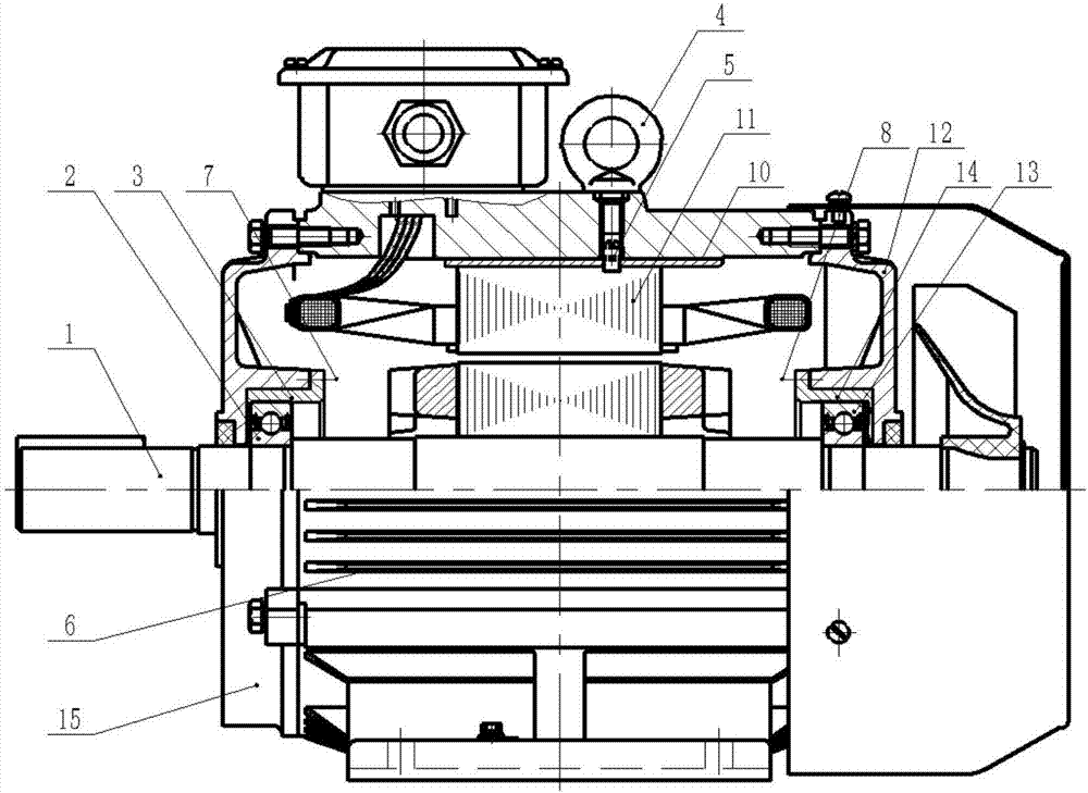
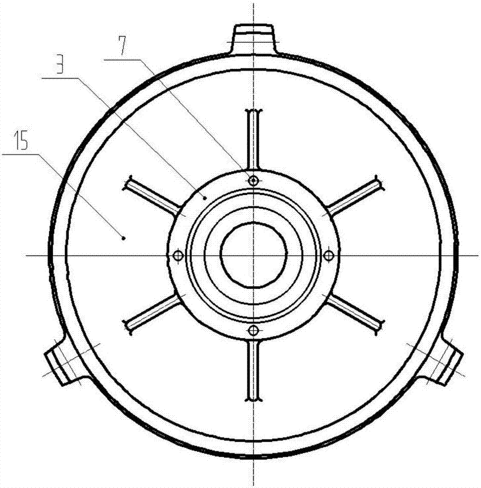
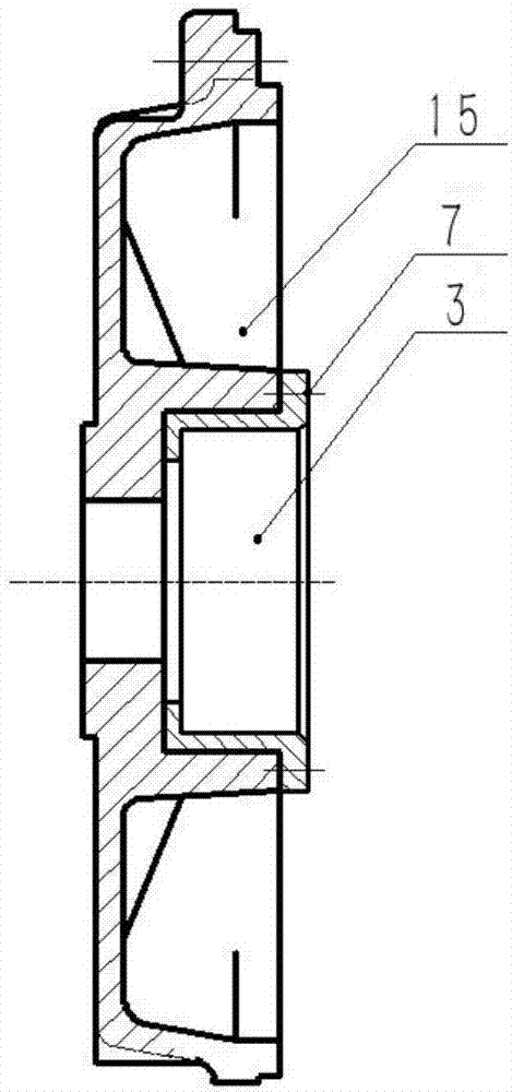
[0024] The rotor vibration isolation sleeve 3 and the stator vibration isolation sleeve 10 are respectively installed in the end cover 15 and the machine base 6 as a transition fit and fixed with set screws to prevent circumferential rotation.

[0025] Such as figure 1 Shown, a kind of low-vibration motor with vibration isolation cover structure is made of motor stator 11, support 6, front end cover 15, rear end cover 12, rotor 1, front bearing 2, rear bearing 13, rotor vibration isolation cover 3, 14. Stator vibration isolation sleeve 10, suspension ring 4, set screw 5, fastening bolt 7, 8 and other motor accessories.

[0026] Take the installation of the relationship between the front cover and various components as an example to illustrate. A stator vibration isolation sleeve 10 structure is added to the inner wall of the motor base 6, and a stator core 11 is installed o...


PUM


Abstract

The invention provides a low-vibration motor with a vibration-isolation sleeve structure, comprising: a motor, a stator vibration-isolation sleeve and a rotor vibration-isolation sleeve; the stator vibration-isolation sleeve is fixed on the inner wall of the motor base, and the stator iron core; the rotor vibration isolation sleeve is installed in the bearing chamber of the motor end cover, and the inner wall of the rotor vibration isolation sleeve is embedded in the bearing. The stator vibration isolation sleeve is made of damping alloy material, which is cylindrical and longer than the length of the stator core in the axial direction of the motor; the rotor vibration isolation sleeve is made of damping alloy material, with an outer flange on the edge, and the surface of the flange is There are screw holes; there is also a bearing block in the rotor vibration isolation sleeve. The invention adds a vibration isolation sleeve structure to the vibration transmission path of the motor to reduce vibration transmission and effectively reduce vibration noise. The installation of the device structure is firm and reliable, and does not affect the mechanical performance of the motor; the structure of the stator and rotor of the motor is not changed, and the electrical performance of the motor is not affected; the installation is convenient, the replaceability means strong versatility, and it is easy to implement.

Description

technical field [0001] The invention belongs to the technical field of motors, and in particular relates to a low-vibration motor with a vibration-isolation sleeve structure. Background technique [0002] The low-vibration design of the motor is the same as the low-vibration design of conventional equipment, mainly focusing on reducing the size of the motor excitation source and optimizing the transmission path of vibration and noise. Among them, the electrical design of the motor generally weakens the electromagnetic force by adopting reasonable groove fit, inclined groove technology, selecting appropriate pitch and groove type and other optimized electromagnetic parameters, reducing the electromagnetic excitation source as the main excitation source of the motor, thereby reducing the electromagnetic force. The vibration of the foot of the small motor; and the structural design of the motor is mainly based on the vibration and noise reduction design of the motor, that is, t...

Claims


Application Information

Patent Timeline
IPC IPC(8): H02K5/24H02K7/08H02K5/04H02K5/02
CPCH02K5/24H02K5/02H02K5/04H02K7/083H02K2213/03
Inventor 李玩幽孔德峰率志君卢熙群闫东生焦殿霖鲁露
Owner HARBIN ENG UNIV
Why Eureka
Try Eureka