
Radioactive material imaging monitoring device

A technology of radioactive substances and monitoring devices, applied in the field of ray detection, can solve the problems of limited imaging field of view, expensive, bulky equipment, etc., to achieve the effect of improving accuracy and reliability, good spatial resolution, and ensuring public safety

Active Publication Date: 2019-11-22
TSINGHUA UNIV
View PDF7 Cites 0 Cited by
  • Summary
  • Abstract
  • Description
  • Claims
  • Application Information

AI Technical Summary

Problems solved by technology

[0003] In related technologies, Geiger counters only have counting intensity information, and cannot obtain the orientation of radioactive sources
Gamma cameras with parallel holes, pinholes or coded plate collimators can be used to image radioactive substances, but the collimators are made of heavy metals, the equipment is bulky and expensive, and the imaging field of view is limited, which is not conducive to large-scale application and popularization , making it difficult to use in open scenarios and mobile applications
The Compton camera has high requirements on the energy resolution of the detector, but it is not suitable for low-energy radioactive sources
2X2 blocks of detectors are used to block the front and back, so that the count on the crystal is related to the direction of the radioactive source, and the radioactive source can be located, but it is only suitable for the direction estimation of a single point radioactive source, and imaging cannot be performed, resulting in inaccurate and reliable monitoring. and effective guarantee of public safety, needs to be improved

Method used


Image

  • Radioactive material imaging monitoring device
  • Radioactive material imaging monitoring device
  • Radioactive material imaging monitoring device

Examples


Embodiment Construction

[0024] Embodiments of the present invention are described in detail below, examples of which are shown in the drawings, wherein the same or similar reference numerals designate the same or similar elements or elements having the same or similar functions throughout. The embodiments described below by referring to the figures are exemplary and are intended to explain the present invention and should not be construed as limiting the present invention.

[0025] The radioactive material imaging monitoring device proposed according to the embodiments of the present invention will be described below with reference to the accompanying drawings.

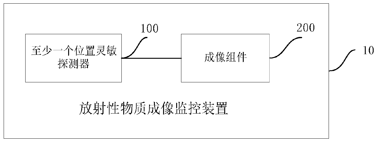
[0026] figure 1 It is a schematic structural diagram of a radioactive material imaging monitoring device according to an embodiment of the present invention.

[0027] Such as figure 1 As shown, the radioactive substance imaging monitoring device 10 includes: at least one position-sensitive detector 100 and an imaging component 200 .

[00...


PUM


Abstract

The invention discloses a radioactive substance imaging monitoring device. The radioactive substance imaging monitoring device comprises at least one position sensitive detector and an imaging assembly, wherein the at least one position sensitive detector is used for acquiring the reception position information of incident rays emitted by a radioactive source, the imaging assembly is used for acquiring spatial distribution images of any radioactive source in a preset spatial scope according to cumulative count distribution of the position information in the preset time, and radioactive substance imaging monitoring is carried out according to the spatial distribution images. The monitoring device is advantaged in that imaging of the radioactive source in any direction in a certain spatial scope can be realized to acquire radioactive source distribution images, radioactive source monitoring is carried out according to the radioactive source distribution images, monitoring accuracy and reliability are improved, public safety is effectively guaranteed, and the monitoring device is simple and easy for realization.

Description

technical field [0001] The invention relates to the technical field of radiation detection, in particular to an imaging monitoring device for radioactive substances. Background technique [0002] Radioactive substances widely exist in nature and are used in industry, agriculture, medical care and other industries. The monitoring of radioactive substances by detecting the radiation emitted by radioactive substances is important to ensure the normal storage and application of radioactive substances in specified places, prevent accidental leakage, loss or illegal transfer, and prevent radioactive substances from being used in terrorist attacks and endangering public safety. significance. [0003] In the related art, the Geiger counter only has counting intensity information, and cannot obtain the orientation of the radioactive source. Gamma cameras with parallel holes, pinholes or coded plate collimators can be used to image radioactive substances, but the collimators are mad...

Claims


Application Information

Patent Timeline
Patent Type & Authority Patents(China)
IPC IPC(8): G01T1/16
CPCG01T1/1603
Inventor 马天予刘亚强王瑞叶青胡安康范鹏许天鹏吕振雷
Owner TSINGHUA UNIV
Learn More