
Pressure detection display device

A display device and pressure technology, applied in the direction of measuring device, measuring force, instrument, etc., can solve the problem of damage to the resistive pressure sensor, and achieve the effect of light and thin

Active Publication Date: 2017-11-10
XIAMEN TIANMA MICRO ELECTRONICS
View PDF5 Cites 8 Cited by
  • Summary
  • Abstract
  • Description
  • Claims
  • Application Information

AI Technical Summary

Problems solved by technology

In the subsequent process of making the display (for example, subsequent peeling, cleaning and other processes), the resistive pressure sensor is easily damaged by the static electricity introduced in the process

Method used


Image

  • Pressure detection display device
  • Pressure detection display device
  • Pressure detection display device

Examples


Embodiment Construction

[0027] The application will be further described in detail below in conjunction with the accompanying drawings and embodiments. It should be understood that the specific embodiments described here are only used to explain related inventions, rather than to limit the invention. It should also be noted that, for ease of description, only parts related to the invention are shown in the drawings.

[0028] It should be noted that, in the case of no conflict, the embodiments in the present application and the features in the embodiments can be combined with each other. The present application will be described in detail below with reference to the accompanying drawings and embodiments.

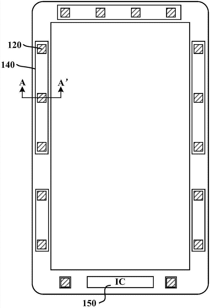
[0029] see Figure 1A Shown is a schematic structural diagram of an embodiment of the pressure detection and display device of the present application, Figure 1B for along Figure 1A The cross-sectional view of A-A' in the middle. It should be noted that, in order to make the drawings reflect th...


PUM


Abstract

The invention discloses a pressure detection display device which includes a substrate, a first semiconductor layer which is provided with a plurality of pressure detection induction units, an insulating layer which covers the first semiconductor layer, a pressure-sensitive detection circuit which is used for providing an input voltage signal for the pressure detection induction units and receiving pressure induction signals collected by the pressure detection induction units, and electrostatic protection rings of which the orthographic projections on the substrate are closed rings, wherein the orthographic projection of each pressure detection induction unit on the substrate is within one of the closed rings. According to the scheme of the invention, an electrostatic protection effect is achieved for the pressure detection induction units, and damage to the pressure detection induction units caused by the accumulation of static charges introduced by the subsequent process in the pressure detection induction units is avoided.

Description

technical field [0001] The present disclosure generally relates to the field of display technology, and in particular, to a pressure detection display device. Background technique [0002] With the development of display technology, only touch position detection can no longer meet the diverse requirements of the interactive operation modes of the human-computer interaction interface presented on the display screen. In addition to detecting the coordinate position of the finger on the display screen plane, it is also necessary to detect the pressure of the finger pressing the display screen, so as to perform corresponding display according to the difference in pressure. [0003] The design of the pressure sensing function in the existing display screen mainly adopts capacitive or resistive pressure sensors. In the design of resistive pressure sensors, in order to avoid affecting the light transmittance of the display area, multiple pressure sensors are usually arranged in th...

Claims


Application Information

Patent Timeline
Patent Type & Authority Applications(China)
IPC IPC(8): G01L1/22
CPCG01L1/2206G01L1/2262
Inventor 林鸿袁永朱在稳
Owner XIAMEN TIANMA MICRO ELECTRONICS
Learn More