Conveying structure and mounting method thereof

An installation method and a technology for connecting joints, applied in the direction of circuits, passing components, electrical components, etc., can solve the problems of low strength of cooling pipe joints and low efficiency of finished products, so as to reduce manual workload, increase yield, and strengthen connections intensity effect

Pending Publication Date: 2017-11-10
苏州三峰激光科技有限公司
View PDF6 Cites 0 Cited by
  • Summary
  • Abstract
  • Description
  • Claims
  • Application Information

AI Technical Summary

Problems solved by technology

[0004] The purpose of the present invention is to provide a conveying structure to improve the existing problems of low strength and low product efficiency of cooling pipe joints
[0005] The purpose of the present invention is to provide an installation method to improve the problems of low strength and low product efficiency of the existing cooling pipe joints

Method used


Image

  • Conveying structure and mounting method thereof
  • Conveying structure and mounting method thereof
  • Conveying structure and mounting method thereof

Examples


Embodiment 1

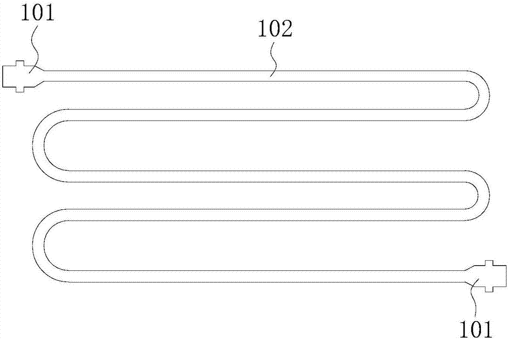
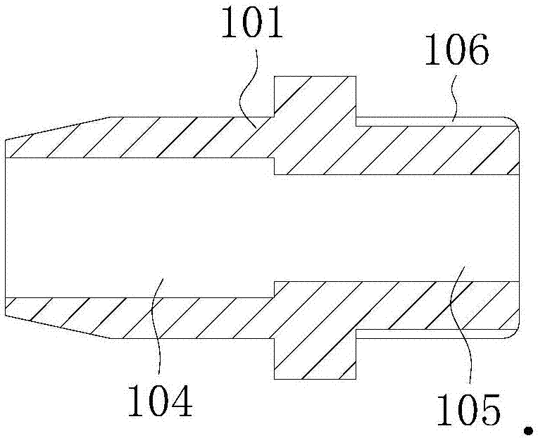
[0051] refer to Figure 1 to Figure 4 , the present embodiment provides a delivery structure, including a connecting joint 101, the connecting joint 101 is provided with a first through hole 104 and a second through hole 105, the first through hole 104 communicates with the second through hole 105, the first through hole 104 is a waist-shaped hole, the second through hole 105 is a circular hole, and the length of the first through hole 104 is greater than the diameter of the second through hole 105 .

[0052] The cooling water pipe 102 is arranged under the power battery, and due to the narrow space and compact structure, its shape must be set to be flat. The first through hole 104 of the conveying structure provided by this embodiment is flat, which can facilitate the installation of the cooling water pipe 102. This connection method can greatly enhance the connection strength between the cooling water pipe 102 and the conveying structure. At the same time, because the first ...

Embodiment 2

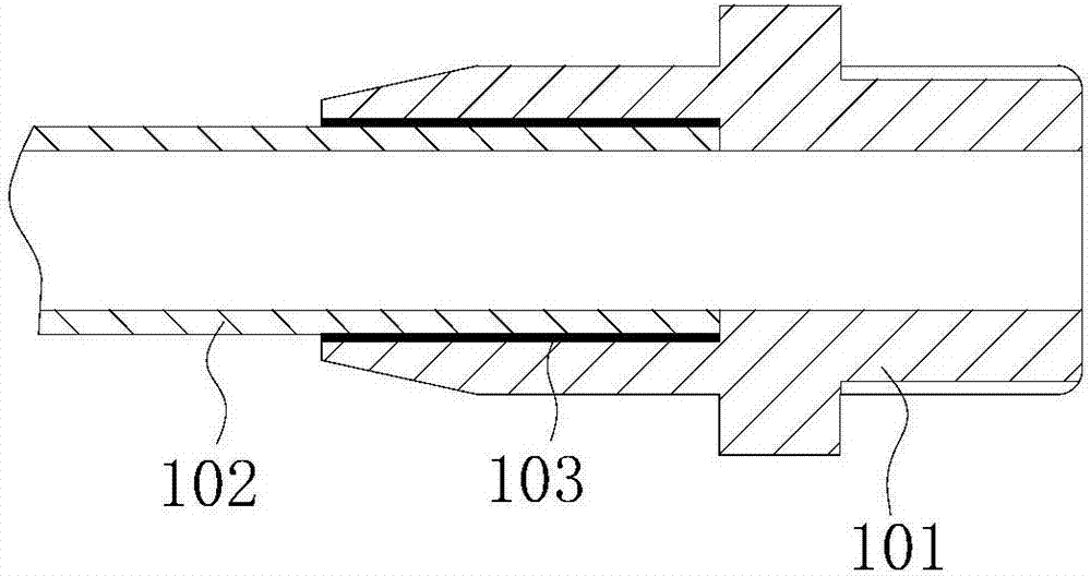
[0060] refer to Figure 5 , the present embodiment provides an installation method, first fill the soldering material 103 in the first through hole 104 of the connecting joint 101 of the delivery structure, then insert the cooling water pipe 102 into the first through hole 104, and then connect the connecting joint Heat treatment is carried out at the first through hole 104 of 101, and finally cooled until the solder is solidified.

[0061] The installation method provided in this embodiment can ensure the connection strength between the connection joint 101 and the cooling water pipe 102 after the cooling water pipe 102 is connected with the connection joint 101, because the connection length and the connection area between the connection joint 101 and the cooling water pipe 102 Larger, so there will be no water leakage problem, and at the same time, the yield of installation can also be improved. Compared with existing technologies such as argon arc welding, the installation...


PUM

PropertyMeasurementUnit
thicknessaaaaaaaaaa

Abstract

The invention provides a conveying structure and a mounting method thereof and belongs to the field of automobile cooling. The conveying structure comprises an attachment joint, a first through hole and a second through hole are formed in the attachment joint, and the first through hole is communicated with the second through hole; the first through hole is a kidney-shaped hole, the second through hole is a circular hole, and the length of the first through hole is larger than the diameter of the second through hole; the mounting method of the conveying structure is used for describing how to install the conveying structure. According to the conveying structure, the first through hole is in a flat shape and can make the installation of a cooling water pipe convenient, and the connection mode can greatly improve the connection intensity of the cooling water pipe and the conveying structure; meanwhile, due to the fact that the shape of the first through hole is identical to that of the cooling water pipe, the finished product ratio during installation is high.

Description

technical field [0001] The invention relates to the field of automobile cooling, in particular to a conveying structure and an installation method thereof. Background technique [0002] The electric vehicle power battery needs a water cooling system to cool it. The cooling system is an indispensable and important part of the car engine. Its function is to exchange the heat around the power battery with the coolant in the cooling system, thereby reducing the temperature of the power battery. , to ensure the normal operation of the power battery and the car engine. Therefore, the performance of the cooling water pipe of the automobile power battery and the sealing performance of the connection directly affect the overall performance of the automobile and the problem of safe driving. In particular, the connection strength and tightness of the inlet and outlet of the cooling coil are important indicators for determining the stable and long-lasting operation of power batteries a...

Claims


Application Information

Patent Timeline
Patent Type & Authority Applications(China)
IPC IPC(8): F16L13/02H01M10/613H01M10/625H01M10/6556H01M10/6568
CPCH01M10/613H01M10/625H01M10/6556H01M10/6568F16L13/0245Y02E60/10
Inventor 吴鑫华梅俊发熊孝经
Owner 苏州三峰激光科技有限公司
Why Eureka
Try Eureka