An AC-DC five-degree-of-freedom dual-spherical hybrid magnetic bearing for a vehicle-mounted flywheel battery
What is Al technical title?
Al technical title is built by PatSnap Al team. It summarizes the technical point description of the patent document.
A hybrid magnetic bearing and flywheel battery technology, which is applied in the direction of magnetic bearings, bearings, shafts, and bearings, can solve problems such as gyro effect and rotor mass aggravation, so as to suppress gyro effect, reduce friction and windage loss, reduce shaft effect on size
Active Publication Date: 2019-02-05
JIANGSU UNIV
View PDF10 Cites 0 Cited by
Summary
Abstract
Description
Claims
Application Information
AI Technical Summary
This helps you quickly interpret patents by identifying the three key elements:
Problems solved by technology
Method used
Benefits of technology
Problems solved by technology
[0003] The purpose of the present invention is to solve the existing problems of the existing magnetic bearings for flywheel batteries, such as the heavier weight of the rotor and the tendency to produce gyro effects, and to propose an AC / DC motor for vehicle flywheel batteries that has a compact structure, small volume, light weight, and can suppress the gyro effect. Five degrees of freedom double spherical hybrid magnetic bearing
Method used
Image
Click on the blue label to locate the original text in one second.
Reading with bidirectional positioning of images and text.
Examples
Embodiment Construction
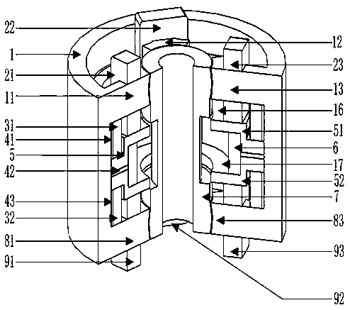
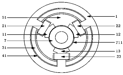
[0024] see figure 1 and figure 2 , the middle of the present invention is the rotor 7, and the outer coaxial sleeve of the rotor 7 has an axial stator 5 and a radial stator.
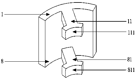
[0025] The radial stator is composed of an upper radial stator 1 and a lower radial stator 8 , and the upper radial stator 1 and the lower radial stator 8 are coaxially arranged along the axial direction of the rotor 7 . The yokes of the upper radial stator 1 and the lower radial stator 8 are coaxially arranged up and down along the axial direction of the rotor 7, and the upper and lower yokes are connected as a whole, and the upper and lower yokes form a hollow cylinder, and the inner cavity of the hollow cylinder That is, the radial stator pole cavity 16 .
[0026] The upper end surface of the upper radial stator 1 is flush with the upper end surface of the rotor 7 , and the lower end surface of the lower radial stator 8 is flush with the lower end surface of the rotor 7 .
[0027] In the radial st...
PUM
Abstract
Provided is an alternating-current and direct-current five-degree-of-freedom hybrid magnetic bearing having dual spherical surfaces for a vehicle-mounted flywheel battery; a radial stator consists of upper and lower radial stators (1, 8) arranged coaxially and having integrally connected yokes; three radial stator poles (11, 12, 13, 81, 82, 83) are arranged along the circumferential direction of each of the upper end of the yoke of the upper radial stator (1) and the lower end of the yoke of the lower radial stator (8); the inner surface of each radial stator pole (11, 12, 13, 81, 82, 83) is a concave spherical surface (211, 811); the upper and lower ends of the intermediate cylinder (73) of a rotor (7) are an upper connection body (72) connected to an upper-end cylindrical body (71) and a lower connection body (75) connected to a lower-end cylindrical body (74), respectively; the side walls of the upper and lower cylindrical bodies (71, 75) are convex spherical surfaces (711, 751); each concave spherical surface (211, 811) correspondingly faces, at its top and bottom, a convex spherical surface (711, 751); an axial stator (5) is nested outside the intermediate cylinder (73); the upper side of an upper axial stator (51) and the lower side of the lower axial stator (52) are each equipped with annular permanent magnets (31, 32); the opposing faces of the upper and lower radial stators (1, 8) and the rotor (7) are spherical structures, eliminating a gyroscopic effect; when the rotor (7) of the magnetic bearing deflects or deviates, the electromagnetic force points to the spherical center of the rotor (7), thus reducing the disturbance torque generated on the rotor (7) by the stator magnetic poles.
Description
technical field [0001] The invention relates to a non-mechanical contact magnetic suspension bearing, in particular to an AC / DC five-degree-of-freedom hybrid magnetic bearing, which is suitable for the magnetic suspension support of a vehicle-mounted flywheel battery of an electric vehicle. Background technique [0002] At present, the main problem restricting the development of electric vehicles is the performance of vehicle power batteries. The vehicle flywheel battery uses the magnetic levitation support and the rotational inertia of the flywheel to realize energy storage, which has the advantages of high charging efficiency, high specific power, small mass, no pollution and long life. Existing flywheel batteries usually use electromagnetic-permanent magnetic hybrid magnetic bearings as the support of the flywheel rotor to achieve suspension with five degrees of freedom in the radial and axial directions. The stator of this hybrid magnetic bearing is a cylindrical struct...
Claims
Application Information
Patent Timeline
Application Date:The date an application was filed.
Publication Date:The date a patent or application was officially published.
First Publication Date:The earliest publication date of a patent with the same application number.
Issue Date:Publication date of the patent grant document.
PCT Entry Date:The Entry date of PCT National Phase.
Estimated Expiry Date:The statutory expiry date of a patent right according to the Patent Law, and it is the longest term of protection that the patent right can achieve without the termination of the patent right due to other reasons(Term extension factor has been taken into account ).
Invalid Date:Actual expiry date is based on effective date or publication date of legal transaction data of invalid patent.