Wave plate screw assembly

A screw and assembly technology, applied in the direction of screws, threaded fasteners, connecting components, etc., can solve problems such as inconvenient use

Inactive Publication Date: 2017-11-07
AVIOUS ENTERPRISE
View PDF5 Cites 0 Cited by
  • Summary
  • Abstract
  • Description
  • Claims
  • Application Information

AI Technical Summary

Problems solved by technology

[0003] When in use, if a washer 14 is to be sleeved on the corrugated board screw 1 to increase the closeness between the screw head 12 and the corrugated board A, it is easier to make the washer 14 difficult to smooth due to the relationship between these hole reaming parts 111. Inserted between the screw head 12 and these reaming parts 111, causing inconvenience in use

Method used


Image

  • Wave plate screw assembly
  • Wave plate screw assembly
  • Wave plate screw assembly

Examples


Embodiment Construction

[0046] The foregoing and other technical content, features and functions of the present invention will be clearly understood in the following detailed description of preferred embodiments with reference to the drawings.

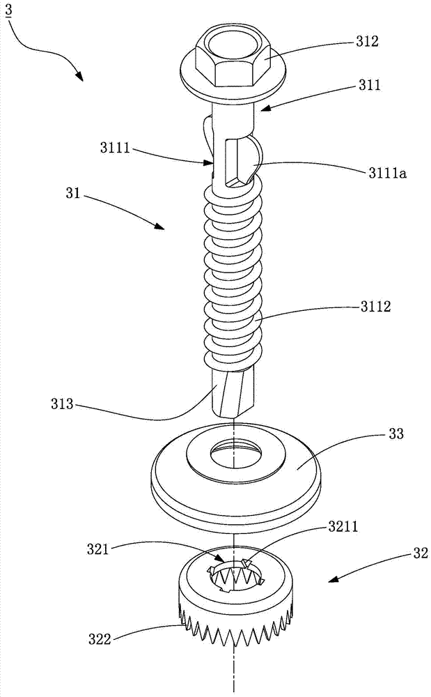
[0047] refer to image 3 , the first preferred embodiment of the corrugated plate screw assembly 3 of the present invention, the corrugated plate screw assembly 3 includes a locking part 31, a hole reaming part 32 that can be sleeved on the locking part 31, and a The washer 33 on the locking member 31; wherein, the locking member 31 has a rod body 311, a screw head 312 arranged on the rod body 311, and a screw head 312 opposite to the screw head 312 and arranged at the other end of the rod body 311 The locking part 313, and the aforementioned rod body 311 is divided into a connecting part 3111 connecting the screw head 312, and a plurality of screw teeth 3112 extending from the connecting part 3111 to the locking part 313, and the connecting part 3111 has at ...


PUM


Abstract

The invention discloses a wave plate screw assembly. The wave plate screw assembly is mainly characterized in that a rod body of a locking part is provided with at least two propping parts; meanwhile, a broaching part is provided with clamping points; in the locking process, the broaching part can be stably and effectively driven to rotate by the locking part through clamping of the propping parts and the clamping points; the cutting capacity and effect of the broaching part are improved; when the propping parts are clamped onto the clamping points, the broaching part can be effectively corrected, and the condition that the broaching part is likely to skew when screwed in is eliminated.

Description

technical field [0001] The invention relates to the technical field of screws, in particular to a corrugated plate screw assembly. Background technique [0002] refer to figure 1 The known corrugated plate screw 1 includes a rod body 11, a screw head 12 provided at one end of the rod body 11, and a locking portion 13 opposite to the screw head 12 and provided at the other end of the rod body 11; wherein, the rod body 11 There are two symmetrically arranged hole reamers 111 and a plurality of circumferentially arranged screw teeth 112 , and the aforementioned hole reamer members 111 are symmetrically arranged between the screw teeth 112 and the screw head 12 . When locking, use the locking part 13 and these screw teeth 112 to screw into the corrugated board A and the skeleton B, and at the same time, these hole reaming parts 111 cut a rotary cutting hole larger than the diameter of the rod body 11 on the corrugated board A, so that An appropriate gap is generated between th...

Claims


Application Information

Patent Timeline
Patent Type & Authority Applications(China)
IPC IPC(8): F16B25/02F16B35/04
CPCF16B25/0036F16B35/041
Inventor 黄显宗
Owner AVIOUS ENTERPRISE
Why Eureka
Try Eureka