
Automatic-held shaft part safety protection frame

A technology for shaft parts and safety protection, applied in the direction of tool storage devices, manufacturing tools, etc., can solve the problems of extrusion damage, inconvenient use, easy deformation, etc., and achieve the effect of saving production sites

Active Publication Date: 2017-11-07
ANHUI WANNAN ELECTRIC MACHINE
View PDF4 Cites 7 Cited by
  • Summary
  • Abstract
  • Description
  • Claims
  • Application Information

AI Technical Summary

Problems solved by technology

[0005] In view of the above situation, in order to overcome the defects of the prior art, the present invention provides a safety protection frame for shaft parts that is automatically tightened, which effectively solves the problem that the shaft parts occupy a large area and are inconvenient to use. Easy to deform, prone to extrusion damage

Method used


Image

  • Automatic-held shaft part safety protection frame
  • Automatic-held shaft part safety protection frame
  • Automatic-held shaft part safety protection frame

Examples


Embodiment Construction

[0020] The specific implementation manners of the present invention will be described in further detail below in conjunction with the accompanying drawings.

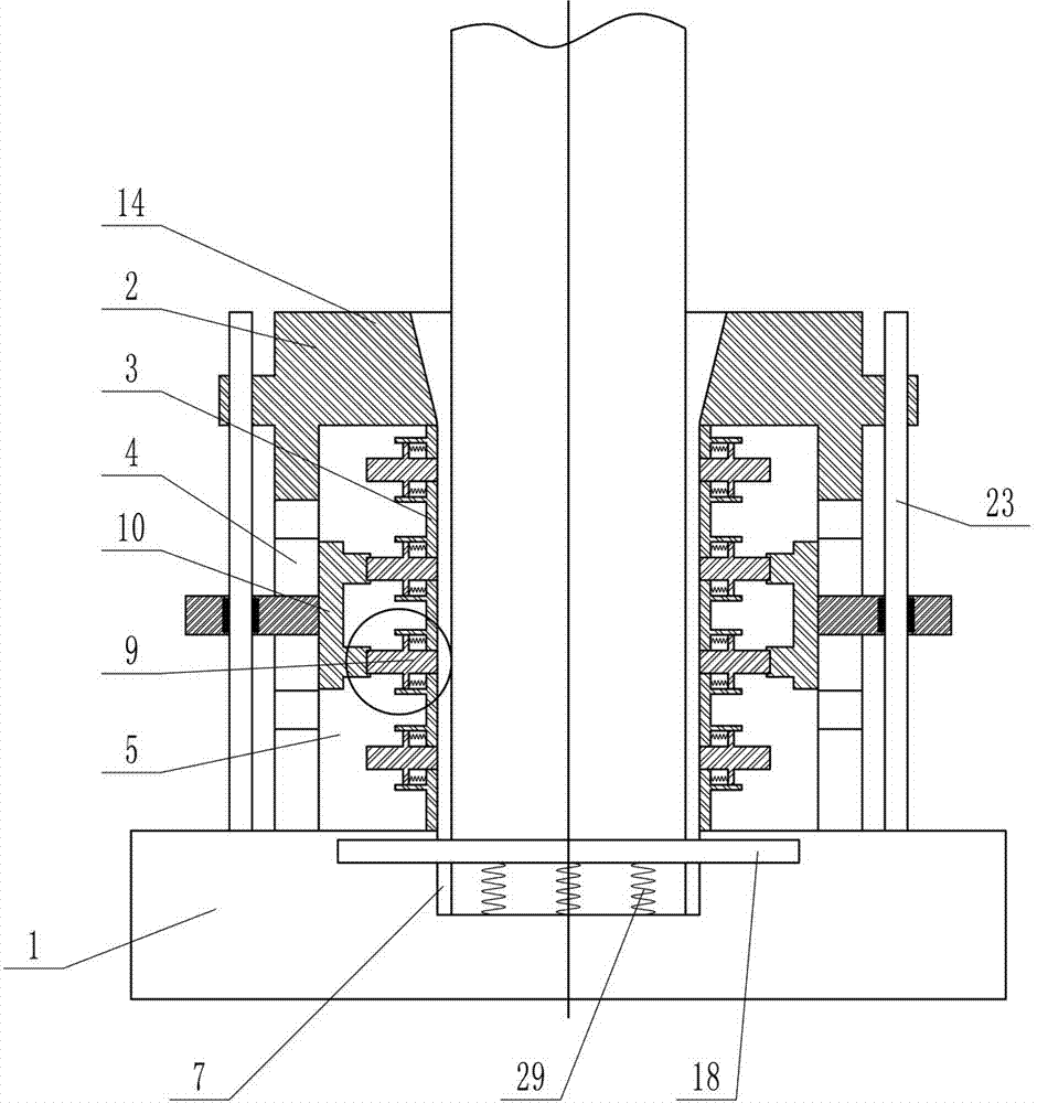
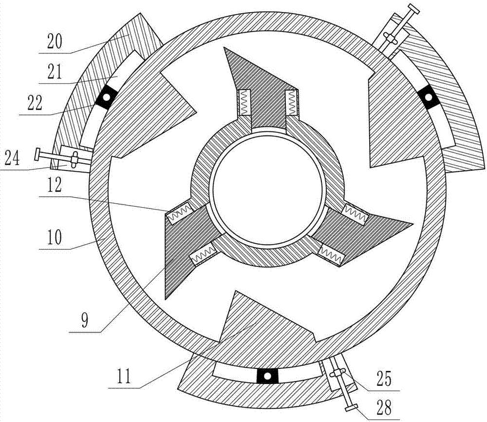
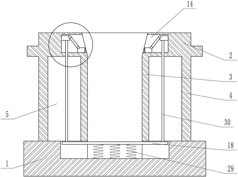
[0021] Depend on Figure 1-10 It can be seen that the present invention includes a base 1, a cylindrical barrel seat 2 is vertically placed on the upper end of the base 1, and the lower part of the barrel seat 2 is an inner and outer two-layer structure composed of an inner sleeve 3 and an outer sleeve 4. An annular cavity 5 is formed between the sleeves 4, a first through hole 6 is opened in the center of the inner sleeve 3, a blind hole 7 concentric with the through hole is opened on the base 1, and a plurality of holes are opened on the side wall of the inner sleeve 3 The first through groove 8, the first through groove 8 is evenly distributed on the circumference of the side wall of the inner sleeve 3, and each first through groove 8 is provided with a pressure block 9 that can slide inside and outside, and the outer...


PUM


Abstract

The invention relates to an automatic-held shaft part safety protection frame, and effectively solves the problems of large floor area of shaft parts, inconvenience in use and easy deformation in transverse placement of shafts. The automatic-held shaft part safety protection frame comprises an annular cavity formed between an inner sleeve and an outer sleeve; a first through groove is formed in the inner sleeve; pressing blocks are arranged in the first through groove; the pressing blocks on the same periphery form a clamping unit; a pressing disc is arranged in the annular cavity; multiple projection blocks are arranged on the inner wall of the pressing disc; first springs are connected between the pressing blocks and the side walls of the inner sleeve; a pressing plate is mounted in a blind hole; a first slide block capable of sliding up and down is mounted on the outer side wall of a first groove; a pull rod is fixed below the first slide block; the pressing plate moves up and down to drive the first slide block to downwards move through the pull rod; the first slide block is hinged with a second slide block capable of sliding inwards and outwards by a connecting rod; and a second spring is connected between the pressing plate and the bottom of the blind hole. The automatic-held shaft part safety protection frame is skillful in structure, convenient in operation and safe and reliable in use.

Description

technical field [0001] The invention relates to the technical field of storage of shaft parts, in particular to a safety protection frame for shaft parts that is automatically tightened. Background technique [0002] Heavy-duty shaft parts are used in a wide range of large-scale heavy machinery. In the production of heavy-duty processing workshops, heavy-duty shaft parts account for a very large proportion. Heavy-duty shaft parts generally have larger diameters and heavier weight. After processing in the workshop During the storage process, heavy shaft parts are generally stored horizontally on wooden sleepers. However, due to the large number of shafts and the long length of shaft parts, horizontal placement takes up a lot of space, and the horizontal shaft parts are easily damaged by collisions. damage. [0003] At the same time, there are also many production workshops that store shafts by stacking many shafts together. Although this storage saves space, but many shafts ...

Claims


Application Information

Patent Timeline
Patent Type & Authority Applications(China)
IPC IPC(8): B25H3/00
CPCB25H3/00
Inventor 李健安郭晓玲王建昆毛春丽刘黎娟
Owner ANHUI WANNAN ELECTRIC MACHINE
Learn More