


Quick Research
Generate reliable direction feasibility study reports for your R&D in just a few steps.

Technical Q&A
Discover and master advanced knowledge NOW. Basics, ideas, possibilities, all at once.

Find Solutions
As an expert in R&D theories, this can generate solutions to your technical problems instantly.

Evaluate Feasibility
Analyze your overall solution with one click, know your potential R&D risks in advance.

Monitor Landscape
Get weekly tech updates, stay abreast of the latest tech innovations and key insights.
Preparing device and method for zero decarburization layer bearing steel wire rod
A zero decarburization layer, preparation device technology, applied in other manufacturing equipment/tools, manufacturing tools, etc., can solve the problems of reduced material utilization rate and dimensional accuracy, inability to achieve continuous operation, low cold heading efficiency, etc., to achieve yield High, high material utilization rate, the effect of improving processing efficiency
- Summary
- Abstract
- Description
- Claims
- Application Information
AI Technical Summary
Problems solved by technology
Method used
Image

Examples
Embodiment 1
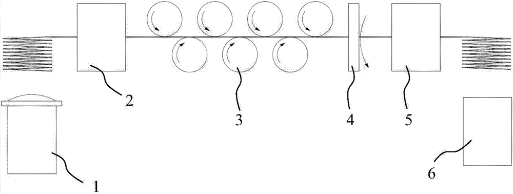
[0028] Such as figure 1 As shown, this embodiment discloses a preparation device for bearing steel wire rod with zero decarburization layer, including a spheroidizing annealing furnace 1, a front cold drawing machine 2, a vertical straightening machine 3, a centerless lathe 4, and a post cold drawing machine 5 and recrystallization annealing furnace 6; the outlet end of the front cold drawing machine 2 is docked with the inlet end of the vertical straightening machine 3, the outlet end of the vertical straightening machine 3 is docked with the inlet end of the centerless lathe 4, the centerless lathe 4 The outlet end is docked with the inlet end of the post-drawing machine 5 . In this embodiment, the upper ring of the spindle disc of the centerless lathe 4 is provided with four symmetrically arranged turning tools. The design of four turning tools on the centerless lathe 4 can accurately and quickly remove the decarburized layer on the surface of the wire rod. Both the spher...
Embodiment 2
[0040] The device, process parameters and process flow included in this example are basically the same as those in Example 1, the difference is that the time for one heat preservation is four hours, and under the premise of ensuring that the bearing steel wire rod is uniformly spheroidized The use time of the spheroidizing annealing furnace is shortened, thereby reducing the use cost of the spheroidizing annealing furnace.
Embodiment 3
[0042] The devices, process parameters and process flow included in this embodiment are basically the same as in Example 2, except that the time for the second heat preservation is three hours. Practice has proved that the second heat preservation time of three hours is more reasonable, avoiding the Too much or too little time for the spheroidizing annealing of the bearing steel wire rod effectively controls the use cost of the spheroidizing annealing furnace.
PUM
 Abstract
Description
Claims
Application Information
 - R&D Engineer
- R&D Manager
- IP Professional
- Industry Leading Data Capabilities
- Powerful AI technology
- Patent DNA Extraction
Browse by: Latest US Patents, China's latest patents, Technical Efficacy Thesaurus, Application Domain, Technology Topic, Popular Technical Reports.
© 2024 PatSnap. All rights reserved.Legal|Privacy policy|Modern Slavery Act Transparency Statement|Sitemap|About US| Contact US: help@patsnap.com