
Strong-swirling mixing and backflow stable-burning incinerator for processing organic pollutant waste gas

A technology of organic pollutants and incinerators, applied in the field of incinerators, can solve the problems of low combustion intensity of incinerators, poor pyrolysis and combustion effects, and environmental pollution, etc., to overcome low combustion intensity, intensification of combustion and heat transfer processes and Optimization, good self-stability effect

Active Publication Date: 2017-11-03
郑州釜鼎热能技术有限公司
View PDF7 Cites 2 Cited by
  • Summary
  • Abstract
  • Description
  • Claims
  • Application Information

AI Technical Summary

Problems solved by technology

[0003] As mentioned above, in order to realize the pyrolysis and combustion of organic pollutants and effectively control the emission of volatile organic pollutants (VOCs), the purpose of the present invention is to provide a strong swirl mixing and reflux stabilization method for treating organic pollutant waste gas. Combustion incinerator can effectively solve the problems of low combustion intensity, poor mixing effect, unreasonable furnace structure, poor pyrolysis and combustion effect of volatile organic pollutants (VOCs), and environmental pollution.

Method used


Image

  • Strong-swirling mixing and backflow stable-burning incinerator for processing organic pollutant waste gas
  • Strong-swirling mixing and backflow stable-burning incinerator for processing organic pollutant waste gas

Examples


Embodiment Construction

[0008] The specific embodiments of the present invention will be further described in detail below in conjunction with the accompanying drawings.

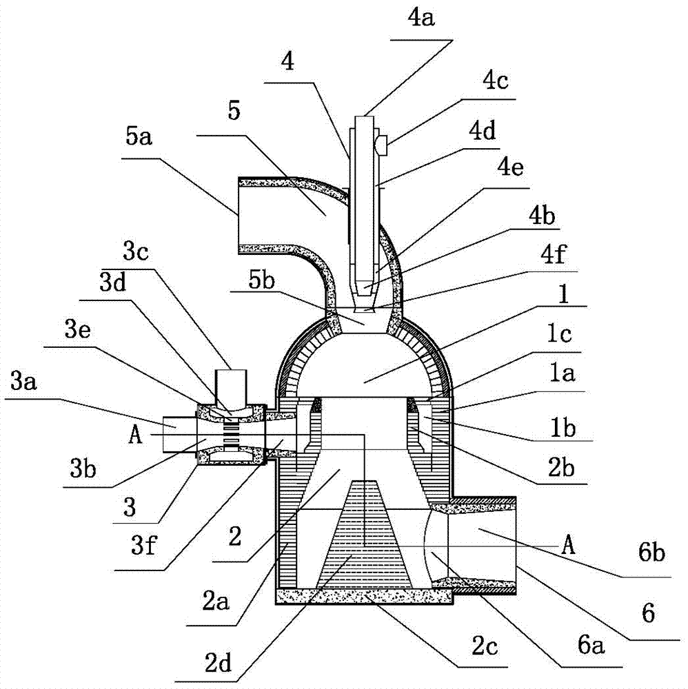
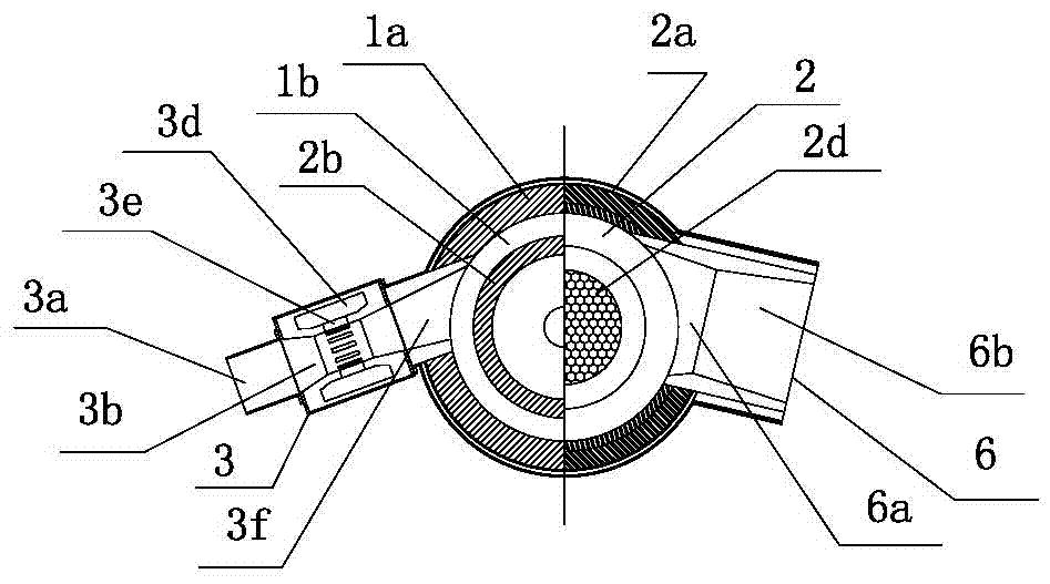
[0009] Depend on Figure 1-Figure 2 Given, the structure of the present invention is that the furnace body is a chamber structure composed of a refractory wall built in a metal furnace shell. The chamber in the furnace body is composed of a combustion mixing chamber 1 and a flue gas mixing chamber 2 connected up and down. The top of the mixing chamber 1 is connected to the exhaust gas introduction pipe 5, and there is an auxiliary burner 4 in the center of the exhaust gas introduction pipe. There is a mixed flue gas exhaust pipe 6 extending horizontally and obliquely out of the furnace body. The combustion mixing chamber 1 is a bell-shaped chamber with a lower opening formed by connecting the upper hemispherical vault and the lower cylinder body up and down. The wall of the combustion mixing chamber is the wall 1a of the combustio...


PUM


Abstract

The invention relates to a strong-swirling mixing and backflow stable-burning incinerator for processing organic pollutant waste gas, and aims to effectively solve the problems that a conventional incinerator is low in combustion intensity, poor in mixing effect and unreasonable in body structure, has poor organic volatile pollutant pyrolysis and combustion effects and pollutes the environment. The strong-swirling mixing and backflow stable-burning incinerator is characterized in that a cavity in an incinerator body consists of a combustion mixing chamber and a flue gas mixing chamber which communicate with each other, an auxiliary combustor is arranged in the center of a waste gas lead-in pipe at the top of the combustion mixing chamber, a main combustor is arranged outside the incinerator body, a mixed flue gas discharge pipe is arranged at the lower part of the flue gas mixing chamber, the upper part of a flue gas mixing chamber wall body is inserted into the combustion mixing chamber, an adjustable loop outlet is formed in the top of a swirling flow pre-mixing combustion loop between the upper part of the flue gas mixing chamber wall body and the lower part of a combustion mixing chamber wall body, a hearth is arranged at the bottom of the flue gas mixing chamber wall body, and a flame stabilizing column is arranged on the hearth. The strong-swirling mixing and backflow stable-burning incinerator is extremely good in self-stability, overcomes the shortcomings of low combustion intensity, poor mixing effect and unreasonable incinerator structure, and achieves the functions of high-intensity combustion mixing and efficient heat and mass transfer, and the investment cost is reduced.

Description

technical field [0001] The invention relates to thermal equipment of the incinerator type, in particular to an incinerator for treating waste gas of organic pollutants with strong swirl mixing and backflow stable combustion. Background technique [0002] For the incinerator (or combustion device) that uses the high-temperature flue gas generated by gas combustion to heat the waste gas of organic pollutants so that it reaches the incinerator (or combustion device) that generates corresponding inorganic gases by decomposition and combustion, the combustion process of gas and its flue gas and organic pollution The heat transfer and mass transfer (mixing) process between the waste gas determines the performance of the incinerator, and the stable and reasonable structure to complete the above functions is also a problem that must be dealt with emphatically. With the advancement of modern industrial technology, higher technical requirements have been put forward for incinerators, ...

Claims


Application Information

Patent Timeline
Patent Type & Authority Applications(China)
IPC IPC(8): F23G7/06F23G5/44F23D14/02
CPCF23D14/02F23G5/44F23G7/06
Inventor 陈维汉陈云鹤杨海涛张佳鹏
Owner 郑州釜鼎热能技术有限公司
Learn More