
Coal-fired power generation system of coal-fired power plant

A technology for power generation systems and thermal power plants, which is applied to engine components, steam engines, variable displacement engines, etc., and can solve problems such as energy waste and large heat energy

Pending Publication Date: 2017-11-03
杨甫在
View PDF0 Cites 4 Cited by
  • Summary
  • Abstract
  • Description
  • Claims
  • Application Information

AI Technical Summary

Problems solved by technology

[0002] Most of the coal-fired power plants in the prior art use coal to burn, and the heating water becomes water vapor to expand and do work. The heat energy required is relatively large, and the heat energy that can be reused is very little. After the water vapor drives the driver to do work, it is almost useless. At most, water can be heated from normal temperature to water of nearly 100 degrees, but water needs a lot of heat energy to change from liquid 100 degrees hydration to 100 degrees water vapor, and coal is needed for heating, which causes a serious waste of energy

Method used


Image

  • Coal-fired power generation system of coal-fired power plant
  • Coal-fired power generation system of coal-fired power plant
  • Coal-fired power generation system of coal-fired power plant

Examples


Embodiment Construction

[0027] The purpose of this specific embodiment is to provide a coal-fired power generation system in a thermal power plant, which has the advantages of energy saving, environmental protection, and high energy utilization rate.

[0028] Hereinafter, an embodiment will be described with reference to the drawings. In addition, the examples shown below do not limit the content of the invention described in the claims in any way. In addition, all the contents of the configurations shown in the following embodiments are not limited to be essential to the solutions of the invention described in the claims.

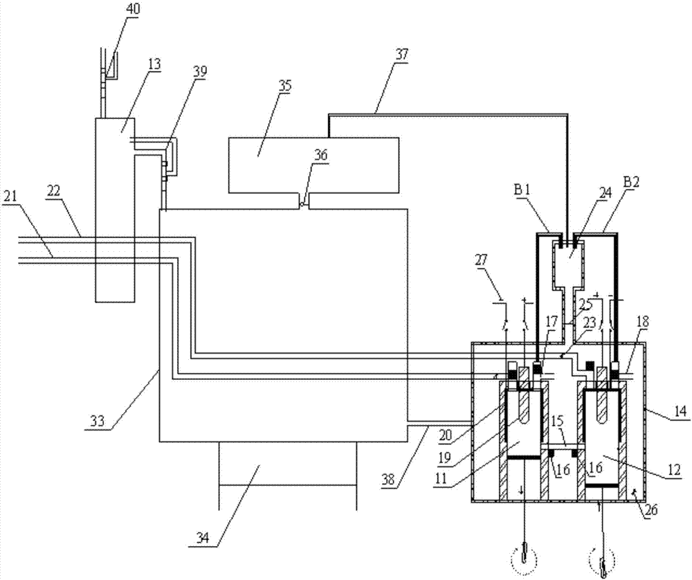
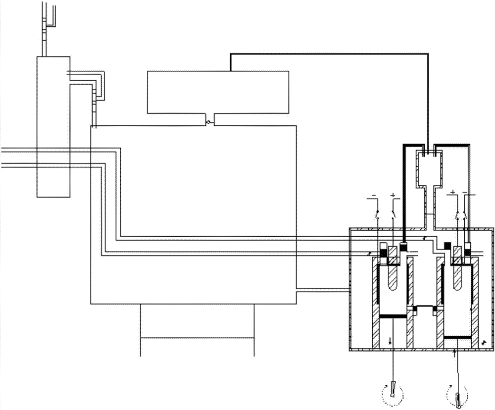
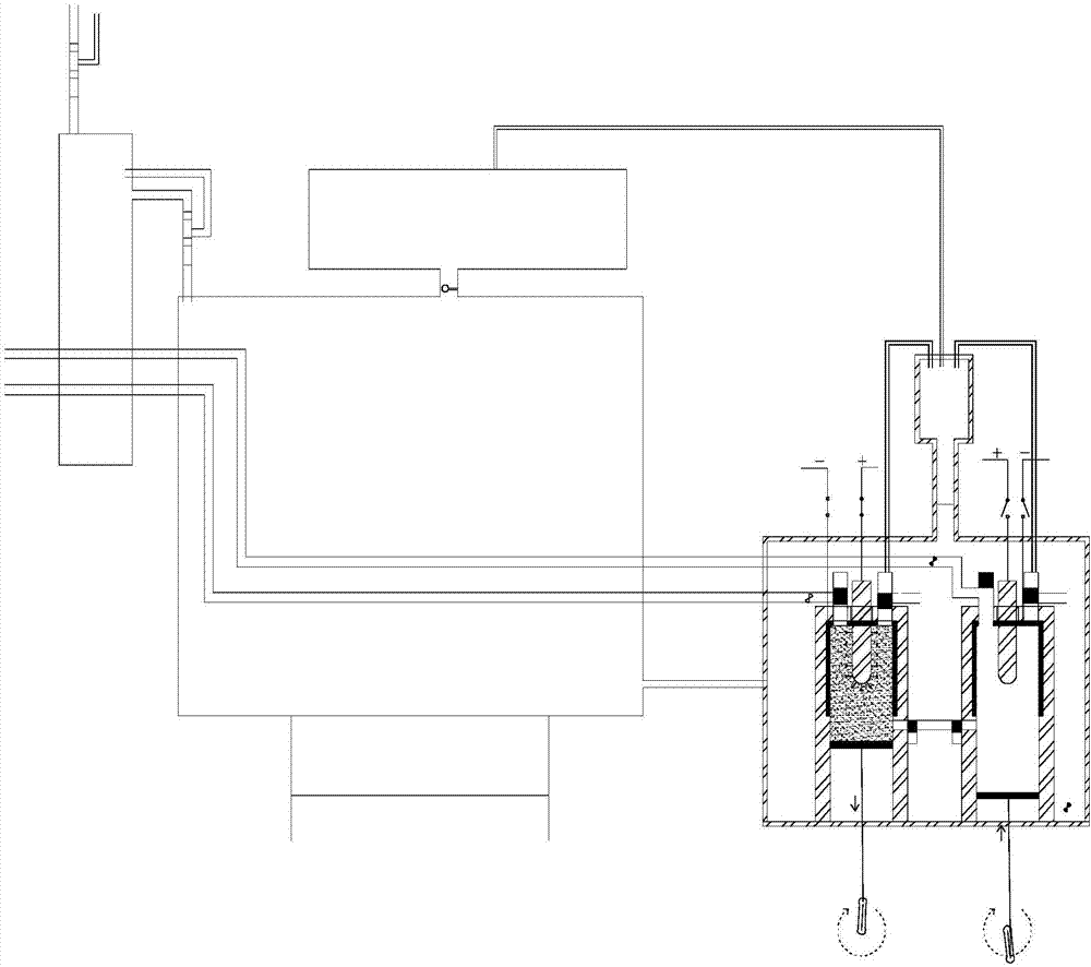
[0029] Please refer to figure 1 , The coal-fired power generation system of a thermal power plant provided in this embodiment includes a makeup water tank 13 , a heating water tank 33 , a high-pressure water tank 14 and a boiler 34 .

[0030] The coal-fired power generation system of the thermal power plant heats the water in the heating water tank 33 through the boiler 34 to f...


PUM


Abstract

The invention discloses a coal-fired power generation system of a coal-fired power plant. The coal-fired power generation system of the coal-fired power plant comprises a water replenishing tank, a water heating tank, a high-pressure water tank, a boiler, an electricity storage and supply system, ionization chambers, pistons which are arranged in the ionization chambers, power output mechanisms which are in transmission connection with the pistons, a power generator which is connected with the power output mechanisms, water spraying systems which are used for spraying the water in the water tank into the ionization chambers, and a controller which is used for controlling the electricity storage and supply system and the water spraying systems; both the two ionization chambers are arranged in the high-pressure water tank; a first high-pressure air cylinder is arranged at the upper end of the high-pressure water tank; the two ionization chambers are communicated with each other through a second high-pressure gas pipe and a first high-pressure gas pipe respectively; high-pressure high-temperature ionization gas in the two ionization chambers provides pressure for the high-pressure water tank through the first high-pressure air cylinder. Through the arrangement, the coal-fired power generation system of the coal-fired power plant provided by the invention has the advantages that the coal-fired power generation system of the coal-fired power plant is energy-saving and environment-friendly, and the energy resource utilization rate is effectively improved.

Description

technical field [0001] The invention relates to the technical field of power plants, and more specifically relates to a coal-fired power generation system of a thermal power plant. Background technique [0002] Most of the coal-fired power plants in the prior art use coal to burn, and the heating water becomes water vapor to expand and do work. The heat energy required is relatively large, and the heat energy that can be reused is very little. After the water vapor drives the driver to do work, it is almost useless. At most, water can be heated from normal temperature to water of nearly 100 degrees, but the hydration of water at 100 degrees in a liquid state into steam at 100 degrees requires a lot of heat energy, and coal is needed for heating, which causes a serious waste of energy. Contents of the invention [0003] In view of this, the present invention raises the temperature of water vapor to about 6000 degrees, so that most of the heat energy can be recycled, and the...

Claims


Application Information

Patent Timeline
Patent Type & Authority Applications(China)
IPC IPC(8): F01B23/10F01B17/04F01B31/00
CPCF01B23/10F01B17/022F01B17/04F01B31/00F01B2170/0476
Inventor 杨甫在
Owner 杨甫在
Learn More