
Tailing liquification floating collecting device

A technology of collection device and liquefaction device, applied in safety devices, mining equipment, earth-moving drilling, etc., can solve the problems of submersible pump motor burnout, uneven concentration of tailings slurry, insufficient material supply, etc., so as to eliminate the large fluctuation of tailings concentration. , High tailings liquefaction efficiency and the effect of reducing construction water

Pending Publication Date: 2017-11-03
GUIZHOU INST OF TECH
View PDF14 Cites 2 Cited by
  • Summary
  • Abstract
  • Description
  • Claims
  • Application Information

AI Technical Summary

Problems solved by technology

Although this method is simple and convenient, the concentration of the tailing mortar is uneven and the flow fluctuates greatly, which leads to the submersible pump often being in a state of insufficient material supply, or even cutting off
Frequent insufficient material supply will have a great impact on the use of submersible pumps, and may easily cause the motor of the submersible pump to burn out
In addition, the water flow can only impact the surface of the tailings pile, and it is difficult to penetrate into its interior, so it takes a long time and the efficiency is low, and the tailings are difficult to disperse
Third, the impact of water flow still has the disadvantages of large water consumption and high operating costs.
Fourth, as the amount of sand mining increases, the submersible pump must be frequently moved from one goaf to the next; not only is the efficiency low, but the operation is also cumbersome

Method used


Image

  • Tailing liquification floating collecting device
  • Tailing liquification floating collecting device
  • Tailing liquification floating collecting device

Examples


Embodiment Construction

[0014] The present invention will be further described below in conjunction with the accompanying drawings and specific embodiments.

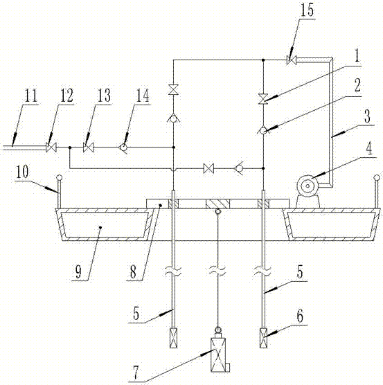
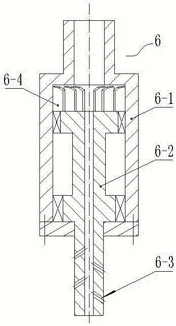
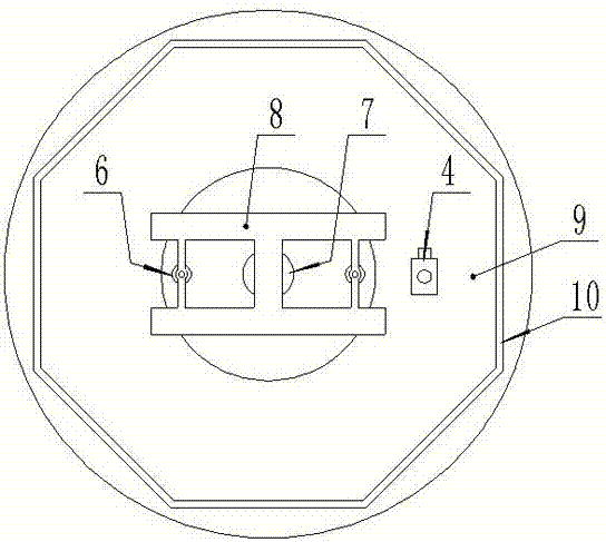
[0015] Such as figure 1 , image 3 Shown: the installation frame 8 is fixed on the circular floating platform 9, and the submersible pump 7 is hoisted below the floating platform by a steel rope (not shown in the figure) fixed on the installation frame 8; around the submersible pump 7 There are two sets of sand stirring and liquefaction devices distributed. The sand-stirring liquefaction device is composed of a spray pipe 5 fixed on a mounting frame 8 and a liquefaction agitation nozzle 6 fixed at the lower port of the spray pipe. Each injection pipe 5 passes through the water supply branch pipe (not shown in the figure) with the water supply check valve 14 and the air supply branch pipe (not shown in the figure) with the air supply check valve 2 respectively, corresponding to the water supply main pipe 11, The air supply main pipe 3 communi...


PUM


Abstract

The invention discloses a tailing liquification floating collecting device, belongs to a tailing collecting device for construction operations such as mineral engineering and safety engineering, and aims at providing a tailing collecting device capable of realize fast loosening and liquification inside of a tailing pile. The collecting device comprises a submerged pump, wherein the submerged pump (7) is hoisted under a floating platform (9) through an installing frame (8); two sets of sand stirring liquification devices are at least distributed on the periphery of the submerged pump (7); each sand stirring liquification device consists of a jet pipe (5) fixed on the installing frame (8) and a sand stirring liquification spray head (6) fixed at a lower end opening of the jet pipe; all jet pipes (5) correspondingly communicate with a water supply main pipe (11) and an air supply main pipe (3) through water supply branch pipes and air supply branch pipes; and the air supply main pipe communicates with an air compressor (4). The tailing liquification floating collecting device has the advantages that the structure is simple; the operation is convenient; the tailing liquification efficiency is high; the construction cost is low; in addition, the work intensity of operators can also be reduced; and the device belongs to the tailing collecting device.

Description

technical field [0001] The invention relates to a tailings collection device, in particular to a collection device used in filling engineering, which can rapidly liquefy the tailings so as to realize pumping pipeline transportation; it belongs to the floating collection of tailings in construction operations such as mining engineering and safety engineering device. Background technique [0002] In the process of mine goaf filling construction, in order to facilitate the collection of tailings for filling in the tailings pond, it is necessary to liquefy the tailings to make it have a certain fluidity so that it can be transported through the pumping pipeline. [0003] In order to ensure the flow effect of the tailing mortar, the method of direct water impact is usually used at present. That is, the hand-held high-pressure water pipe directly impacts and dilutes the deposited tailings pile. The tailings are gradually diluted and fluid under the action of water flow, and then ...

Claims


Application Information

Patent Timeline
IPC IPC(8): E21F15/00
CPCE21F15/00
Inventor 邓代强崔波段瑜
Owner GUIZHOU INST OF TECH
Learn More