Inspection well mouth cutting device and inspection well mouth construction method

A cutting device and inspection well head technology, which is applied in the field of engineering construction, can solve the problems that the advantages of prefabricated inspection well cover module assembly cannot be fully utilized, the bottom of the hole cannot be guaranteed to be flat, and the road takes a long time to improve cutting efficiency. High dimensional accuracy and hole quality, short cutting period

Active Publication Date: 2017-11-03
袁奥
View PDF5 Cites 7 Cited by
  • Summary
  • Abstract
  • Description
  • Claims
  • Application Information

AI Technical Summary

Problems solved by technology

[0005] The above-mentioned cylindrical sinkhole at the head of the inspection well generally adopts the traditional method of powerful blowing or drilling rig emptying. The above-mentioned top-down powerful crushing method will have a great adverse effect on the stability and safety of the surrounding structures, and at the same time, the labor intensity Large, inefficient, and takes up a long time on the road. Although in recent years, with the improvement of the level of mechanization, cutting methods have also been used, but the above cutting methods are all top-down cutting methods, but it is still impossible to ensure the bottom of the hole. The bottom of the hole still depends on the traditional strong blow to break it, and the above method cannot give full play to the advantages of prefabricated manhole cover module assembly

Method used


Image

  • Inspection well mouth cutting device and inspection well mouth construction method
  • Inspection well mouth cutting device and inspection well mouth construction method
  • Inspection well mouth cutting device and inspection well mouth construction method

Examples


Embodiment Construction

[0031] combine Figure 1 to Figure 4 , the present invention is further described:

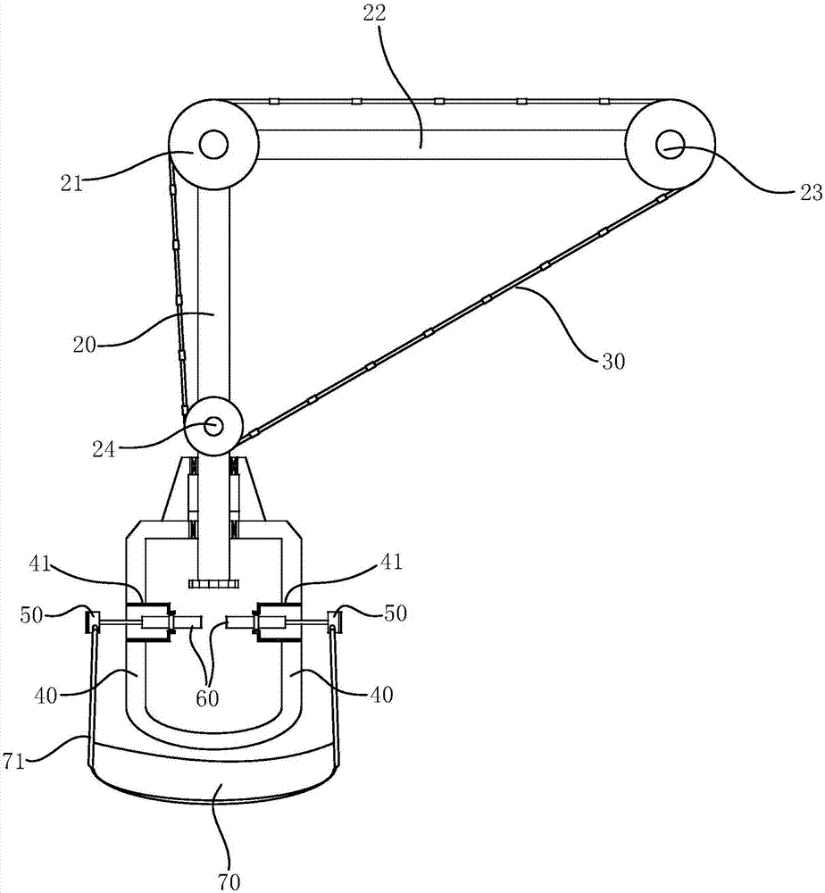
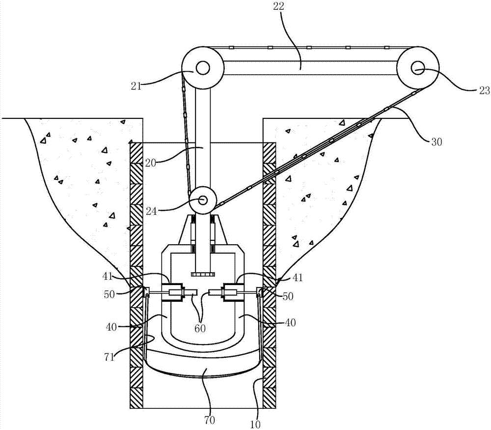
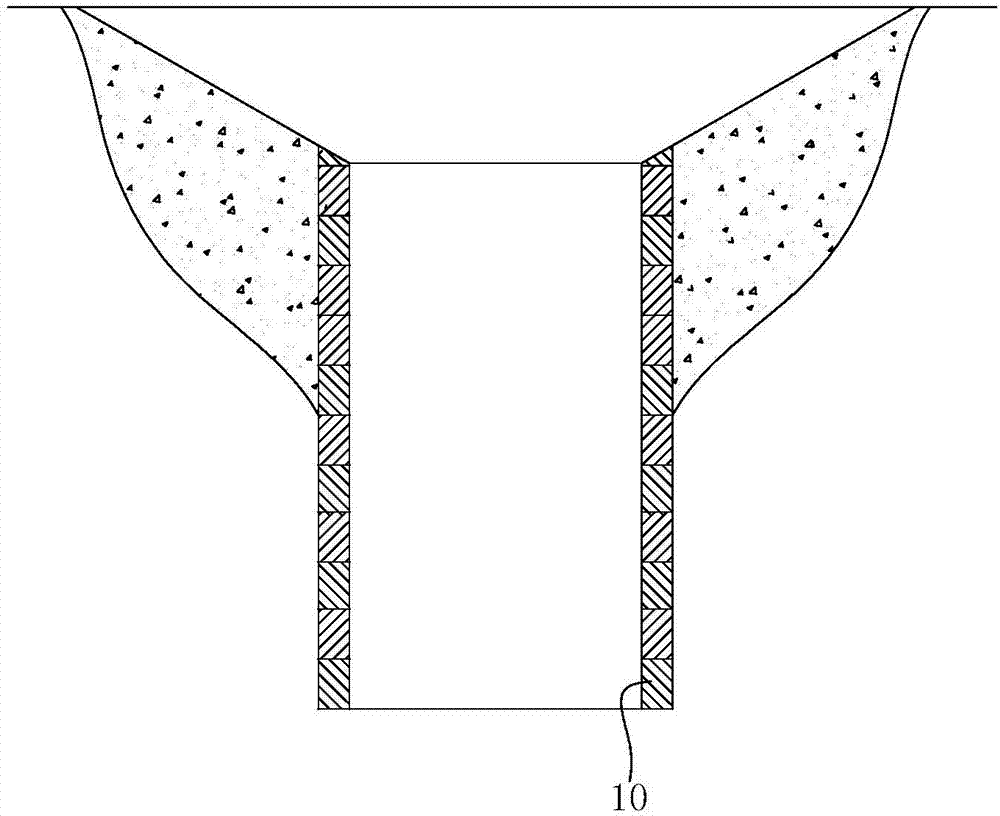
[0032] A cutting device for the wellhead of the inspection well, comprising a positioning mechanism extending into the wellhead of the inspection well 10, a support rod 20 is arranged vertically on the positioning mechanism, the rod core of the support rod 20 is the same core as the inspection well 10, and the driving mechanism drives the support The rod 20 rotates, the upper end of the support rod 20 is provided with a wire saw 30, and the wire saw 30 passes through the well wall of the inspection shaft 10 and extends obliquely upward;

[0033] combine figure 1 with figure 2 As shown, the above-mentioned wire saw 30 arranged obliquely facilitates the construction of the wellhead of the inspection shaft 10, and starts the driving mechanism so that the support rod 20 rotates in the well hole of the inspection shaft 10, thereby realizing the cutting operation of the wellhead of the inspection...


PUM


Abstract

The invention relates to an inspection well mouth cutting device. The inspection well mouth cutting device comprises a positioning mechanism extending into an inspection well mouth. A supporting rod is vertically arranged on the positioning mechanism. The rod core of the supporting rod is the same as an inspection well. A driving mechanism drives the supporting rod to rotate. The upper end of the supporting rod is provided with a rope saw. The rope saw penetrates through the well wall of the inspection well and obliquely extends upwards. By means of the obliquely arranged rope saw, the inspection well mouth can be constructed conveniently. The driving mechanism is started to make the supporting rod rotate in a wellhole of the inspection well so as to realize cutting operation on the inspection well mouth. Through the obliquely arranged rope saw, the cut well mouth is made in a cone-frustum shape. Thus, an inspection well lid module matched with the wellhole of the inspection well is also in a cone-frustum shape and just needs to be prefabricated in advance.

Description

technical field [0001] The invention relates to the technical field of engineering construction, in particular to a cutting device for a manhole head and a construction method for the manhole head. Background technique [0002] Traditional inspection well covers and wellhead systems are sporadic components that require on-site assembly operations, and most of them are manually operated, which leads to long construction work, low construction quality, frequent diseases, and high costs. The scars on the face of the city that will never be removed. [0003] In order to solve the problem that the traditional manhole cover and wellhead system are easily damaged, the applicant's application is called "An Integrated Manhole Cover Module and Its Construction Method" (authorization number: CN104963362B), which can effectively solve the problem that the wellhead system of the manhole in the prior art is easily damaged. The problem is that it includes a hollow cylindrical module body,...

Claims


Application Information

Patent Timeline
Patent Type & Authority Applications(China)
IPC IPC(8): B28D1/08B28D7/00
CPCB28D1/088B28D7/00E02D29/1445
Inventor 袁奥施长顺
Owner 袁奥
Why Eureka
Try Eureka