Eureka AIR delivers breakthrough ideas for toughest innovation challenges, trusted by R&D personnel around the world.

Gear forming grinding machine tool

A technology for forming, grinding and processing machine tools, which is applied to the parts of grinding machine tools, gear cutting machines, metal processing equipment, etc. It can solve the problems that gears cannot be milled, affect the processing efficiency of machine tools, and difficult to locate, and achieve simple and convenient disassembly operations. Effective sliding and reliable guarantee, improving the effect of guiding sliding accuracy

Active Publication Date: 2017-11-03
YIYANG KANGYI MACHINERY DEV
View PDF20 Cites 5 Cited by
  • Summary
  • Abstract
  • Description
  • Claims
  • Application Information

AI Technical Summary

Problems solved by technology

[0003] In the prior art, milling machines are often used to process drum-shaped teeth, but gears cannot be milled after heat treatment, and drum-shaped teeth require higher machining accuracy than ordinary gears, and positioning is difficult, so milling machines and milling cutters cannot meet drum-shaped teeth. The use requirements of high-precision machining quality of teeth, and the flexible adjustment and processing of drum-shaped teeth of different specifications and shapes cannot be realized. In addition, when the modified grinding wheel has been working for a period of time, it needs to be trimmed to restore the grinding performance and correct geometry. The frequent disassembly and assembly of the shaped grinding wheel is not only time-consuming and laborious, but also affects the machining efficiency of the machine tool

Method used


Image

  • Gear forming grinding machine tool
  • Gear forming grinding machine tool
  • Gear forming grinding machine tool

Examples


Embodiment Construction

[0063] Embodiments of the technical solutions of the present invention will be described in detail below in conjunction with the accompanying drawings. The following examples are only used to illustrate the technical solutions of the present invention more clearly, and therefore are only examples, rather than limiting the protection scope of the present invention.

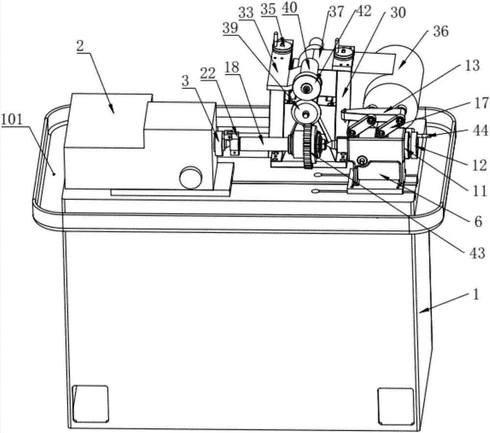
[0064] Such as figure 1 and figure 2 As shown, the present invention provides a gear forming grinding machine tool, including a bed 1, a numerically controlled dividing head 2, a gear centering device, a gear clamping device, a swing device, and a grinding and finishing device; the bed 1 is A box structure, such as Figure 9 As shown, there is an installation base 101 on the bed 1, and the numerical control indexing head 2 is installed on the installation base 101, and the numerical control indexing head 2 is provided with a tooth groove conversion mechanism, and the tooth shape centering device includes a base ...


PUM


Abstract

The invention belongs to the technical field of gear machining equipment and provides a gear forming grinding machine tool comprising a machine tool body; a mounting stand of the machine tool body is provided with a numerical control indexing head, a tooth profile centring device, a gear clamping device, a swing device and a grinding and dressing device; the numerical control indexing head is provided with a tooth space conversion mechanism; the tooth profile centring device comprises a base slidably located on the mounting stand, the base is provided with a position correcting mechanism, and a first centre is slidably arranged in the base and is connected with a first regulating mechanism; the swing device comprises a swing arm mounted in a swing groove of the machine tool body in a limited swing way; the grinding and dressing device comprises supporting plates slidably mounted at two sides of the swing arm, and a second regulating mechanism and a locating mechanism are arranged between the supporting plates and the swing arm, and each of the two supporting plates is provided with a shaping grinding wheel and a dressing wheel. The grinding wheel disclosed by the invention can be used while being repaired, so that the machining precision and efficiency of a drum gear are increased; and the gear forming grinding machine tool can be suitable for flexibly-regulated machining of drum gears with different specifications.

Description

technical field [0001] The invention relates to the technical field of gear processing equipment, in particular to a gear forming and grinding machine tool. Background technique [0002] The crown-shaped tooth is modified along the tooth length direction to improve the radial, axial and angular errors caused by shaft installation errors. It has the advantages of strong bearing capacity, large angular displacement compensation and high transmission efficiency. In addition, the crown-shaped tooth The surface improves the contact condition of the inner and outer teeth, avoids the disadvantages of straight tooth edge extrusion and stress concentration under the condition of angular displacement, and at the same time improves the contact condition of the tooth surface, reduces noise, and prolongs the service life of the gear. Long service life maintenance cycle. [0003] In the prior art, milling machines are often used to process drum-shaped teeth, but gears cannot be milled af...

Claims


Application Information

Patent Timeline
Patent Type & Authority Applications(China)
IPC IPC(8): B23F1/02B23F23/06B24B53/075B24B53/12
CPCB23F1/02B23F23/06B24B53/075B24B53/12Y02P70/10
Inventor 石卫民刘智伟尹少雄
Owner YIYANG KANGYI MACHINERY DEV
Why Eureka
Eureka Blog
Learn More