
Structure applying the glass fiber-reinforced resin foam and manufacturing method therefor

A glass fiber and manufacturing method technology, applied in chemical instruments and methods, applications, synthetic resin layered products, etc., can solve problems such as delamination of surface and core material and decrease in toughness that have not been publicly solved, and achieve excellent physical properties, combined with Enhanced, small deflection effect

Active Publication Date: 2017-10-31
HANKUK CARBON CO LTD
View PDF7 Cites 2 Cited by
  • Summary
  • Abstract
  • Description
  • Claims
  • Application Information

AI Technical Summary

Problems solved by technology

[0010] However, the above-mentioned published patents focus on the technology of enabling polyurethane foam to have excellent thermal insulation properties even at a small thickness, and therefore do not disclose solutions to the problems of delamination between the surface and the core material and reduction in toughness. specific technology
[0011] In addition, conventionally there is no disclosed technique on the bending fatigue resistance of the carrier structure

Method used


Image

  • Structure applying the glass fiber-reinforced resin foam and manufacturing method therefor
  • Structure applying the glass fiber-reinforced resin foam and manufacturing method therefor
  • Structure applying the glass fiber-reinforced resin foam and manufacturing method therefor

Examples


Embodiment

[0075] 1. Phases S1 and S2

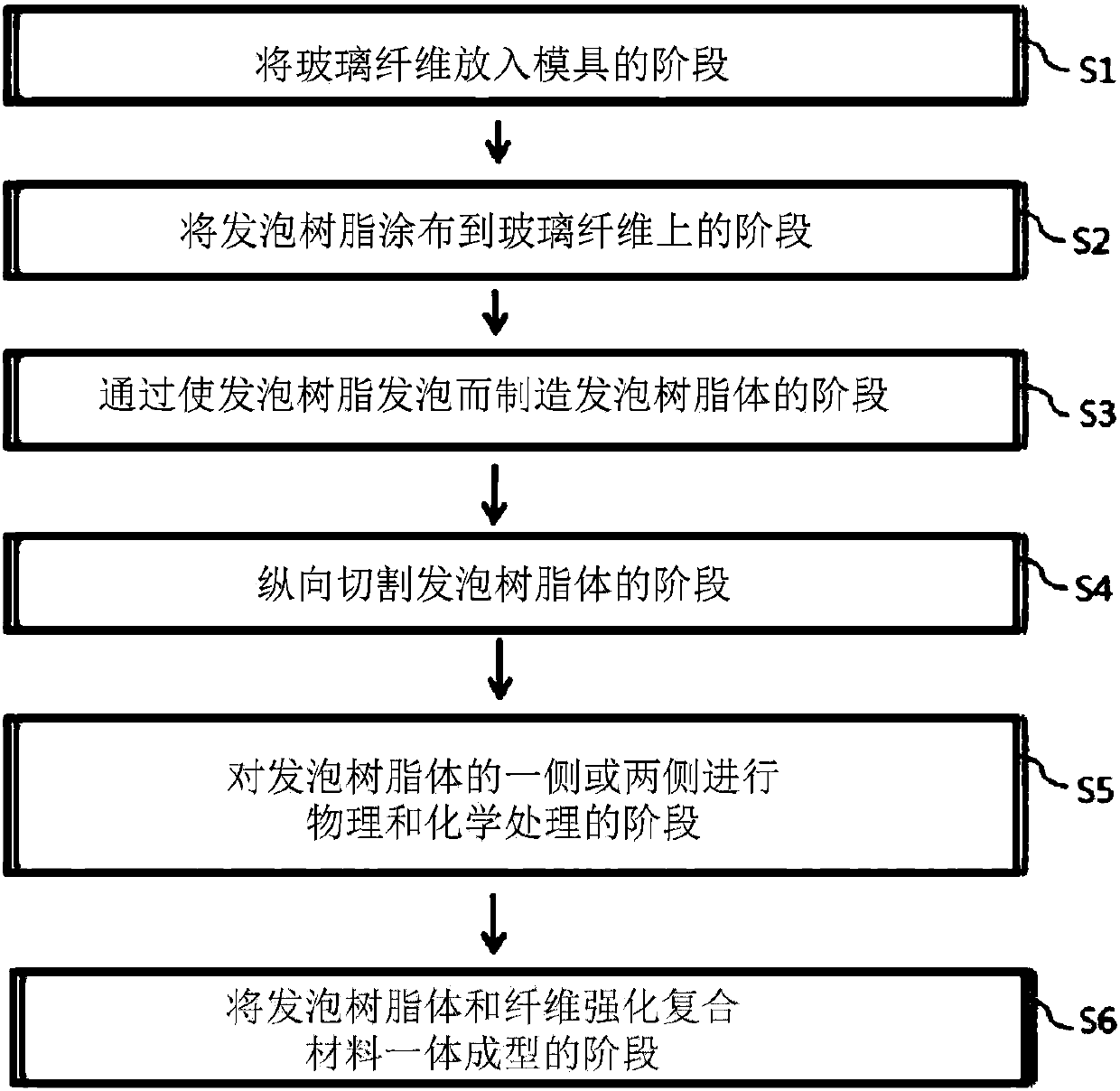
[0076] Figure 3a , 3b It is a cross-sectional view showing the manufacturing method in stages S1 to S2 of the manufacturing method of the carrier sandwich structure of the present invention. refer to Figure 3a , 3b , GCSM (Glass Continuous Strand Mat) consisting of glass continuous fibers was placed on a mold, and polyurethane was sprayed onto the GCSM.

[0077] 2. Stage S3

[0078] Figure 3c It is a cross-sectional view showing the manufacturing method at stage S3 of the manufacturing method of the carrier sandwich structure of the present invention. refer to Figure 3c , foaming the polyurethane by a reaction between the foamed polyurethane on the GCSM and the supplied blowing agent, thereby producing a foamed resin body.

[0079] 3. Stage S4

[0080] Figure 4 It is a cross-sectional view showing the manufacturing method at stage S4 of the manufacturing method of the carrier sandwich structure of the present invention. refer to F...


PUM


Abstract

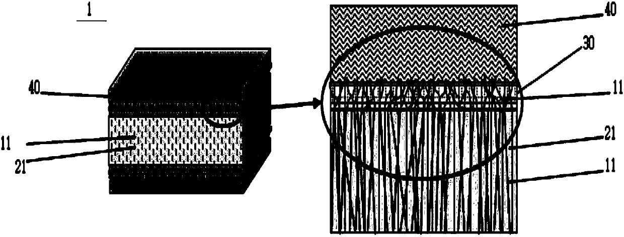
The invention relates to a vehicle sandwich structure and a manufacturing method thereof. The vehicle sandwich structure according to the present invention is characterized as follows: being composed of a foamed resin article in sheet form forming the core, a fiber-reinforced composite layer forming a surface material that is located on one or both sides of the foamed resin article in thickness direction; forming a binding layer of core and surface materials between the foamed resin article and the fiber-reinforced composite layer; a large number of glass fibers being inserted within said foamed resin article; more than 70% of total glass fibers being the glass fibers which form an angle between the longitudinal direction of each glass fiber and said foamed resin article, the angle of which satisfying a range from 45 DEG to 90 DEG; more than 70% of total glass fibers being a glass fiber that satisfies a range of smaller than or equal to 90 degrees; the exposed glass fiber being impregnated and bound to the binding layer and the fiber-reinforced composite layer, wherein one or both ends of the glass fiber are exposed on the entire foamed resin article. Also, it is characterized by the height of the glass fiber which is exposed above the foamed resin article being 0.5 to 10 mm.

Description

technical field [0001] The present invention relates to a carrier structure using a foamed resin body containing glass-reinforced fibers and a manufacturing method thereof, and more particularly to a carrier structure having excellent fatigue resistance and a manufacturing method thereof: Physical and chemical surface treatment is carried out in the foamed resin body of the part, so that the glass fibers arranged in the thickness direction in the foamed resin body are exposed at a fixed height on the foamed resin body, thus the foamed resin body and the glass fiber exposed In the integral molding process of the fiber-reinforced composite material, the bond between the foamed resin body with exposed glass fibers and the fiber-reinforced composite material is improved. Background technique [0002] Generally, polyurethane foam is a porous material on which the sponge is made from polyols and diisocyanates, and it exists in two types, flexible and rigid. Flexible types of poly...

Claims


Application Information

Patent Timeline
IPC IPC(8): B32B27/12B32B27/04B32B7/12B32B17/04
CPCB32B7/12B32B17/04B32B27/12B32B2260/046B32B2260/021B32B2307/304B32B2307/552B32B5/08B32B5/145B32B5/20B32B3/30B32B2250/02B32B2250/03B32B2250/40B32B2262/02B32B2262/0261B32B2262/106B32B2262/14B32B2266/0228B32B2266/025B32B2266/0278B32B2266/0285B32B5/12B32B5/245B32B2262/101B32B2307/546B32B2605/00C08J5/04C08J5/043C08J9/22B29C44/1266B29C44/34B29C69/001B29C70/44B29C70/443B29C70/48B29L2009/00B29L2031/30B32B7/04B32B2305/022B32B2305/08
Inventor 金正喆金旼奎李承雨崔炳敏
Owner HANKUK CARBON CO LTD
Learn More