
Machine tool for processing horseshoe-shaped slots of drill bit

A horseshoe-shaped and drill bit technology, which is applied in the field of machine tools for processing drill bit horseshoe-shaped grooves, can solve the problems of drilled holes not straight, drill bit axis bending, deviation, etc.

Active Publication Date: 2017-10-31
ZHEJIANG PULANKA ROCK TOOLS CO LTD
View PDF8 Cites 0 Cited by
  • Summary
  • Abstract
  • Description
  • Claims
  • Application Information

AI Technical Summary

Problems solved by technology

[0003] When using this method to process the drill bit, the end of the drill bit will be squeezed by the milling cutter, making the end of the drill bit tilt to the side away from the milling cutter, which will cause a certain amount of bending of the drill bit axis
If the axis of the drill bit is bent, the phenomenon of deviation will occur during drilling, resulting in a non-straight drilled hole, which is not conducive to the withdrawal of the drill bit and the insertion of the detonator.

Method used


Image

  • Machine tool for processing horseshoe-shaped slots of drill bit
  • Machine tool for processing horseshoe-shaped slots of drill bit
  • Machine tool for processing horseshoe-shaped slots of drill bit

Examples


Embodiment 1

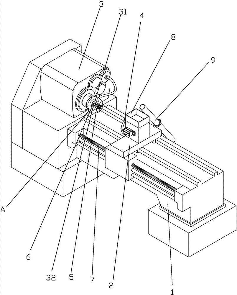
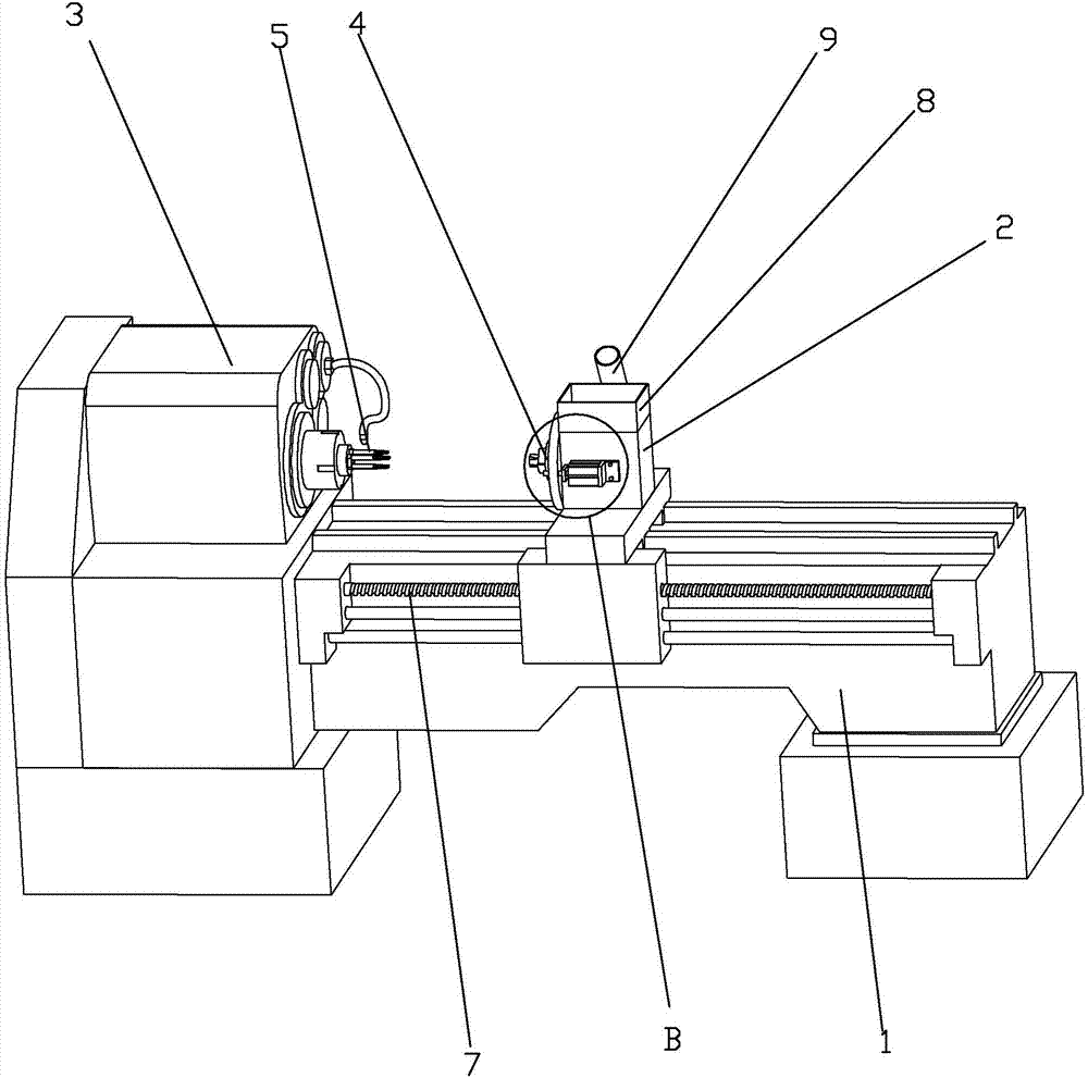
[0037] Embodiment 1: as figure 1 , figure 2 with image 3 As shown, a machine tool for processing drill bit horseshoe-shaped grooves, including a frame 1, a power head 3 is provided at one end of the frame 1, and a first power output portion 32 is provided on the side of the power head 3 facing the middle of the frame 1, The power head 3 is provided with a power source, and the power source is generally a motor, and the first power output part 32 and the motor are shifted through gears. The conical milling cutter 5 that is used for milling is fixed on the power output part 31, is also provided with 4 power output parts 31 on the same side of the first power output part 32 outer power head 3, is all fixed with conical milling cutter 5 on the power output part 31. The milling cutter 5 has the same taper as the angle of inclination of the horseshoe-shaped groove 16. All the power output parts 31 are evenly distributed along the circumference and correspond to the positions of...

Embodiment 2

[0042] Embodiment 2: as Figure 7 , Figure 8 with Figure 9 As shown, the difference between embodiment 2 and embodiment 1 is that the fixing base 2 is fixed in the middle of the frame 1, and the power heads 3 are arranged on both sides of the fixing base 2. Both sides of the fixed base 2 facing the power head 3 are provided with pneumatic chucks 4 for clamping the drill bit 15; at the same time, the two power heads 3 are provided with four power output parts 31, which can have four horseshoe-shaped grooves. The drill bit 15 of 16 is processed. Starting from the first power output portion 32 , the other power output portions 31 are named as the second power output portion 31 , the third power output portion 31 and the fourth power output portion 31 in the counterclockwise direction. The first power output part 32 and the third power output part 31 interfere with the inner ring of the belt 6, and the second power output part 31 and the fourth power output part 31 interfere ...


PUM


Abstract

The invention discloses a machine tool for processing horseshoe-shaped slots of a drill bit. The machine tool comprises a rack, wherein a power head and a fixing seat for fixing the drill bit are arranged on the rack; power output parts are arranged on the power head; milling cutters are clamped on the output parts; a guide rail and a drive component for driving the power head or the fixing seat to move on the guide rail in a reciprocating way are further arranged on the rack; at least two power output parts are arranged on the power head; the tapered milling cutters are clamped on the power output parts; the positions of the tapered milling cutters correspond to the positions of the horseshoe-shaped slots of the drill bit to be processed; and the tapers of the tapered milling cutters are consistent to tilt angles of the horseshoe-shaped slots on the drill bit. The machine tool for processing the horseshoe-shaped slots of the drill bit can prevent an axis of the drill bit from bending when the horseshoe-shaped slots are processed.

Description

technical field [0001] The invention relates to drill bit processing equipment, in particular to a machine tool for processing drill bit horseshoe grooves. Background technique [0002] Drill bit is a common tool in various mining engineering or stonework. Generally, at least two horseshoe-shaped grooves for chip removal are evenly distributed on the outer circumference of the bit head, and the axis of the horseshoe-shaped grooves and the axis of the bit are inclined to facilitate chip removal during use. The processing of the horseshoe-shaped groove on the drill bit is generally processed by milling. The existing processing method is generally to set the axis of the drill bit and the milling cutter to be inclined, and then make the drill bit move to the milling cutter along the horizontal direction to interfere with the milling cutter to process the horseshoe-shaped groove. When a horseshoe-shaped groove is processed in place, the drill bit first Move away from the millin...

Claims


Application Information

Patent Timeline
IPC IPC(8): B23C3/28
CPCB23C3/28B23C2220/36
Inventor 沈国华
Owner ZHEJIANG PULANKA ROCK TOOLS CO LTD
Learn More