mechanical chuck

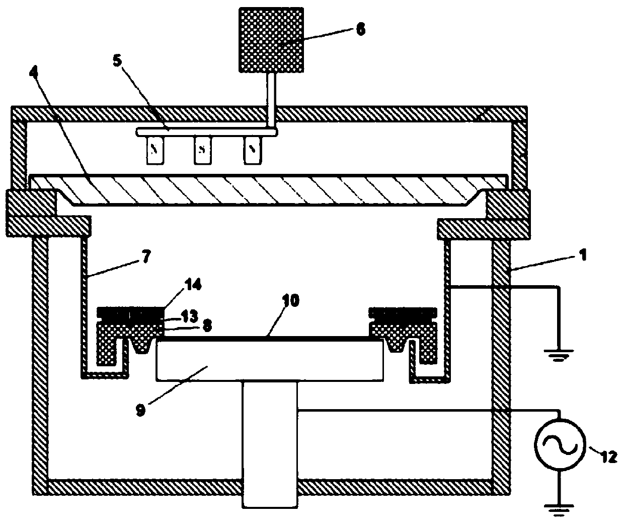
A mechanical chuck and snap ring technology, applied in metal material coating process, vacuum evaporation plating, coating and other directions, can solve the problems of high RF voltage of the wafer 10, deviation of the position of the wafer 10, deformation of the snap ring 8, etc. Avoid spark phenomenon, reduce RF energy loss, avoid deformation effect

Active Publication Date: 2020-04-28
BEIJING NAURA MICROELECTRONICS EQUIP CO LTD
View PDF2 Cites 0 Cited by
  • Summary
  • Abstract
  • Description
  • Claims
  • Application Information

AI Technical Summary

Problems solved by technology

Therefore, it is necessary to input higher radio frequency power to the susceptor 9 to meet the process requirements, but this will cause the radio frequency voltage on the wafer 10 to be too high, which is prone to sparking
[0007] Its two, the plasma bombardment shield 14 will make its temperature rise, and the temperature of snap ring 8 will rise rapidly thereupon, after many times of processes, snap ring 8 is easy to produce deformation due to high temperature, which is easy to cause Consequences such as positional deviation and sparking of wafer 10

Method used


Image

  • mechanical chuck
  • mechanical chuck
  • mechanical chuck

Examples


Embodiment Construction

[0027] In order to enable those skilled in the art to better understand the technical solution of the present invention, the mechanical chuck provided by the present invention will be described in detail below in conjunction with the accompanying drawings.

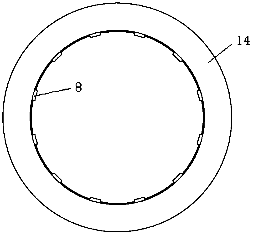
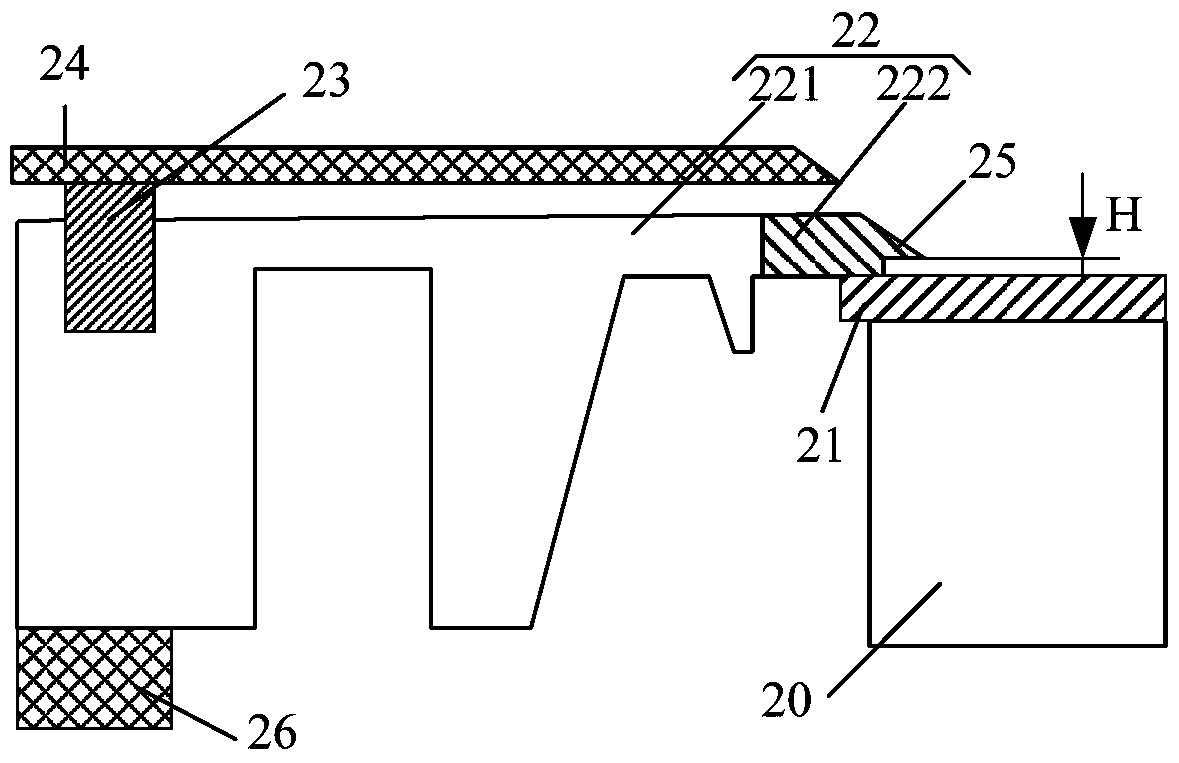
[0028] image 3 A partial sectional view of the mechanical chuck provided by the first embodiment of the present invention. Figure 4 It is a top view of the mechanical chuck provided by the first embodiment of the present invention. Please also refer to image 3 and Figure 4 , the mechanical chuck includes a base 20 for carrying a wafer 21 and a snap ring assembly, the snap ring assembly includes a snap ring 22, an insulating ring 23 and a shield ring 24, wherein the snap ring 22 is used to fix the wafer 21 on the base 20, it includes an annular body 221, which is made of insulating material such as ceramics or quartz. Moreover, a pressing portion 222 is provided on the inner peripheral wall of the annular body 221, ...


PUM


Abstract

The invention provides a mechanical chuck comprising a base for bearing a wafer and a clamp ring assembly. The clamp ring assembly comprises a clamp ring, an insulation ring and a shield ring, and the clamp ring is used for fixing the wafer. The insulation ring is arranged on the clamp ring and used for supporting the shield ring, and the shield ring is used for shielding the upper surface of the clamp ring. The clamp ring comprises a ring-shaped body made of an insulation material. A tight pressing part is arranged on the inner peripheral wall of the ring-shaped body and used for pressing the marginal area of the upper surface of the wafer. The tight pressing part is made of a metal material. According to the mechanical chuck provided by the invention, the radio frequency energy loss on the shield ring can be reduced, the radio frequency efficiency can be improved, the spark phenomenon is avoided, bombardment of plasma on the shield ring can further be reduced, thus the temperature of the shield ring can be decreased, and thus the situation that the clamp ring deforms due to the over high temperature is avoided.

Description

technical field [0001] The invention relates to the technical field of semiconductor manufacturing, in particular to a mechanical chuck. Background technique [0002] In the manufacturing process of integrated circuits, physical vapor deposition (Physical Vapor Deposition, hereinafter referred to as PVD) technology is usually used to deposit materials such as metal layers on wafers. With the widespread application of Through Silicon Via (TSV) technology, PVD technology is mainly used to deposit barrier layers and copper seed layers in the through silicon vias. During the TSV deposition process, a mechanical chuck is usually used to fix the silicon wafer. [0003] figure 1 It is a cross-sectional view of an existing PVD device. Such as figure 1 As shown, the PVD equipment includes a reaction chamber 1, and a target 4 is arranged on the top of the reaction chamber 1, which is electrically connected to an excitation power supply (not shown in the figure), and a magnetron is...

Claims


Application Information

Patent Timeline
Patent Type & Authority Patents(China)
IPC IPC(8): C23C14/50
CPCC23C14/50
Inventor 张璐
Owner BEIJING NAURA MICROELECTRONICS EQUIP CO LTD
Why Eureka
Try Eureka