
Special riveting machine for vacuum booster

A vacuum booster and riveting technology, applied in transportation, packaging, vehicle parts, etc., can solve problems such as difficult simultaneous feeding of riveting knives, inconsistent deformation of riveting parts, and inability to effectively guarantee sealing performance, etc.

Pending Publication Date: 2017-10-24
SHANDONG AOYOU AUTOMOBILE BRAKING SYST
View PDF12 Cites 0 Cited by
  • Summary
  • Abstract
  • Description
  • Claims
  • Application Information

AI Technical Summary

Problems solved by technology

However, due to the influence of the oil inlet sequence and the pipeline, it is difficult for each hydraulic cylinder to feed the riveter at the same time, and the riveting time of each part is inconsistent, resulting in inconsistent deformation of the riveting part of the vacuum booster product, so that the riveting part of the vacuum booster product The depth of the riveting point is inconsistent, the sealing performance cannot be effectively guaranteed, and the appearance quality of the riveting point is difficult to control, which greatly reduces the qualified rate of the vacuum booster assembly

Method used


Image

  • Special riveting machine for vacuum booster
  • Special riveting machine for vacuum booster
  • Special riveting machine for vacuum booster

Examples


Embodiment Construction

[0021] Below in conjunction with accompanying drawing and embodiment, further elaborate the present invention. In the following detailed description, certain exemplary embodiments of the invention are described by way of illustration only. Needless to say, those skilled in the art would realize that the described embodiments can be modified in various different ways, all without departing from the spirit and scope of the present invention. Accordingly, the drawings and description are illustrative in nature and not intended to limit the scope of the claims.

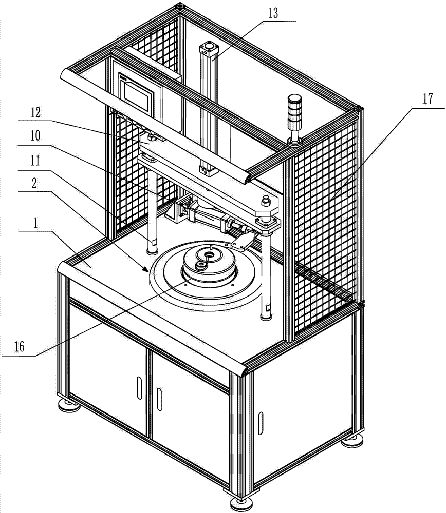
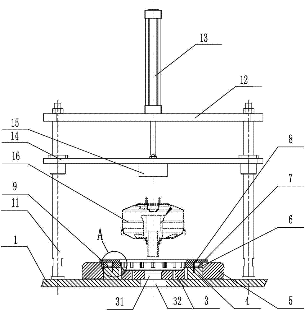
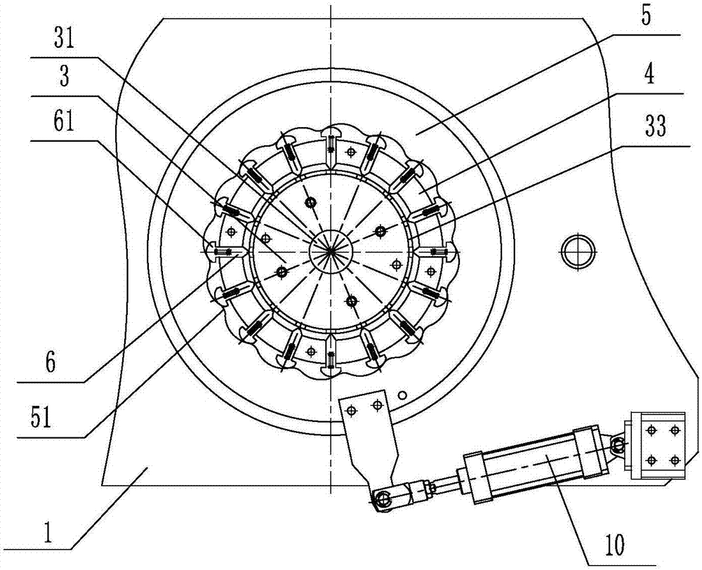
[0022] Such as figure 1 , figure 2 , image 3 and Figure 4 As shown, the vacuum booster riveting machine includes a stand 1, and the riveting device 2 is provided on the stand 1, and the riveting device 2 includes a positioning plate for placing the booster on the stand 1. 3. The outer side of the positioning plate 3 is fixedly fitted with a riveting guide device, on which riveting knives 6 that slide radially are ...


PUM


Abstract

The invention discloses a special riveting machine for a vacuum booster. The special riveting machine comprises a rack, wherein a riveting device is arranged on the rack; the riveting device comprises a location disc installed on the rack and used for placing the vacuum booster; a riveting guide device is fixedly installed at the outer side of the location disc in a sleeving manner; radially-sliding riveting knives are distributed on the riveting guide device in the circumferential direction; the riveting knives are connected with a return limit device; an outer riveting disc is rotationally installed at the outer side of the riveting guide device in a sleeving manner; riveting bulges corresponding to the outer ends of the riveting knifes are distributed on the inner circumferential wall of the outer riveting disc in a bulging manner in the circumferential direction; and a riveting propelling device is arranged between the rack and the outer riveting disc. The special riveting machine disclosed by the invention is capable of realizing simultaneous feeding of the riveting knifes, thereby ensuring the same riveting time for parts and the same depth of riveting points of riveting parts of a vacuum booster product, and effectively ensuring the sealing performance and the appearance quality of the riveting points.

Description

technical field [0001] The invention relates to an assembly technology of an automobile vacuum booster, in particular to a special riveting machine for a vacuum booster. Background technique [0002] The riveting of the vacuum booster is an essential process in the production of the vacuum booster. At present, the riveting process of the vacuum booster is to control several hydraulic cylinders through a hydraulic station. For example, there are 16 common riveting points corresponding to 16 The hydraulic cylinders are respectively driven by each hydraulic cylinder to advance the riveter of the working head to realize the riveting of the riveter. However, due to the influence of the oil inlet sequence and the pipeline, it is difficult for each hydraulic cylinder to feed the riveter at the same time, and the riveting time of each part is inconsistent, resulting in inconsistent deformation of the riveting part of the vacuum booster product, so that the riveting part of the vacuu...

Claims


Application Information

Patent Timeline
Patent Type & Authority Applications(China)
IPC IPC(8): B21D39/00B21D53/88
CPCB21D39/00B21D53/88
Inventor 王林成王华村
Owner SHANDONG AOYOU AUTOMOBILE BRAKING SYST
Learn More