Method for laser surface hardening treatment of local end surface of thin-wall piece by workpiece clamping
A technology of hardening treatment and laser heat treatment, which is applied in the field of laser surface hardening treatment, can solve the problems of scrapped parts, damage to the flatness of the end surface of the workpiece, failure to meet the hardness requirements, etc., and achieve the effect of simple structure and convenient operation
- Summary
- Abstract
- Description
- Claims
- Application Information
AI Technical Summary
Problems solved by technology
Method used
Image
Examples
Embodiment 1
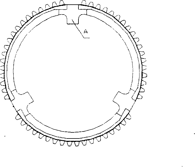
[0014] Embodiment 1: Blocks in the synchronization ring of the gearbox, such as figure 1 At A, the width is 14mm, the thickness is 3mm, and the end faces on the left and right sides of the block need to be hardened. Its specific technological process is as follows:
[0015] 1. First, make two rectangular splints with the same shape. One end face of the long side of the two splints is processed into a profiling surface that is close to the shape of the block in the synchronous ring of the gearbox, and the length of the splint is greater than the end face of the block in the synchronous ring of the gearbox. The long side is 25mm, and there are 1 to 2 through holes in the vertical direction of the splint surface on both sides of the splint, which correspond to each other and are larger than Φ3mm, which is convenient for passing through the bolts and clamping the workpiece; the splint width is 10mm, and the splint thickness is: 2mm, the splint is 0.5mm higher than the end face of...
Embodiment 2
[0020] Embodiment 2: Blocks in the synchronization ring of the gearbox, such as figure 1 At A, the width is 14mm, the thickness is 3mm, and the end faces on the left and right sides of the block need to be hardened. Its specific technological process is as follows:
[0021] 1. First, make two rectangular splints with the same shape. One end face of the long side of the two splints is processed into a profiling surface that is close to the shape of the block in the synchronous ring of the gearbox, and the length of the splint is greater than the end face of the block in the synchronous ring of the gearbox. The long side is 25mm, and there are 1 to 2 through holes in the vertical direction of the splint surface on both sides of the extended part of the splint, which correspond to each other and are larger than Φ3mm, which is convenient for passing through the bolts and clamping the workpiece; the width of the splint is 11mm, and the thickness of the splint is: 7mm, the splint i...
Embodiment 3
[0026] Embodiment 3: ultra-thin model tool
[0027] 1. First make two rectangular splints with the same shape. One end face of the long side of the two splints is processed into a profiling surface close to the shape of the ultra-thin sample tool, and the length of the splint is 25mm longer than the long side of the ultra-thin sample tool end. The length of the splint There are 1 to 2 through holes in the direction vertical to the surface of the splint on both sides of the outlet part, which correspond to each other and are larger than Φ3mm, which is convenient for passing through the bolts and clamping the workpiece; the width of the splint is 10mm, the thickness of the splint is 7mm, and the splint is thinner than The end face height of the model tool: 0.2mm.
[0028] 2. Next, place a piece of plywood on both sides of the large surface of the ultra-thin sample tool. The respective profiling end faces of the two splints should be parallel to the end face of the ultra-thin sam...
PUM
| Property | Measurement | Unit |
|---|---|---|
| depth | aaaaa | aaaaa |
| width | aaaaa | aaaaa |
| thickness | aaaaa | aaaaa |
Abstract
Description
Claims
Application Information
 - R&D
- Intellectual Property
- Life Sciences
- Materials
- Tech Scout
- Unparalleled Data Quality
- Higher Quality Content
- 60% Fewer Hallucinations
Browse by: Latest US Patents, China's latest patents, Technical Efficacy Thesaurus, Application Domain, Technology Topic, Popular Technical Reports.
© 2025 PatSnap. All rights reserved.Legal|Privacy policy|Modern Slavery Act Transparency Statement|Sitemap|About US| Contact US: help@patsnap.com


