
Low voltage cable current test recorder

A current testing, low-voltage cable technology, applied in the direction of voltage/current isolation, only measuring current, measuring current/voltage, etc., can solve the problems of inability to judge, wrong household relationship, misjudgment, etc., to achieve accurate and reliable measurement data, make up Data mutation, the effect of ensuring accuracy requirements

Inactive Publication Date: 2017-10-20
STATE GRID CORP OF CHINA +1
View PDF5 Cites 2 Cited by
  • Summary
  • Abstract
  • Description
  • Claims
  • Application Information

AI Technical Summary

Problems solved by technology

Because it is impossible to observe the direction of the cable under the surface, it is impossible to judge which cable carries which users, resulting in the problem of unclear correspondence between transformers and users
First, when the power supply company wants to overhaul and shut down a certain transformer, it does not know which users need to be notified in advance of the power outage
Second, when the power supply company assesses the line loss, it needs to know in advance which users the transformer is carrying, and then calculate the line loss by dividing the electricity sales of all users of the transformer on the day by the total power supply of the day on the transformer general table, and the relationship between the users is wrong. As a result, the real line loss cannot be calculated
[0005] 1. Power frequency induction method: In the low-voltage user station area, the cable outlets are complicated, and induction is easy to occur between adjacent cables, which can easily cause misjudgment or even failure to judge
[0006] 2. Audio induction method: identify the cable direction and burial depth through the twisting characteristics of the cable pitch, which is very easy to be misjudged by external interference, and it is almost impossible to judge in the low-voltage cable user area where multiple cables are staggered.
[0007] 3. Pulse current method: Since the pulse current method requires a power outage to apply a pulse signal, it cannot meet the power outage requirements in low-voltage user areas that require extremely high power supply reliability.
[0008] 4. Cable identification method based on the principle of electromagnetic induction: This method requires multiple cables to form a loop, and it is still not suitable for low-voltage user cable areas where the cables are deeply buried and cannot make a loop judgment.
Therefore, in the field of low-voltage cable identification, there is no better way

Method used


Image

  • Low voltage cable current test recorder
  • Low voltage cable current test recorder
  • Low voltage cable current test recorder

Examples


Embodiment Construction

[0050] Specific embodiments of the present invention will be described in detail below in conjunction with the accompanying drawings.

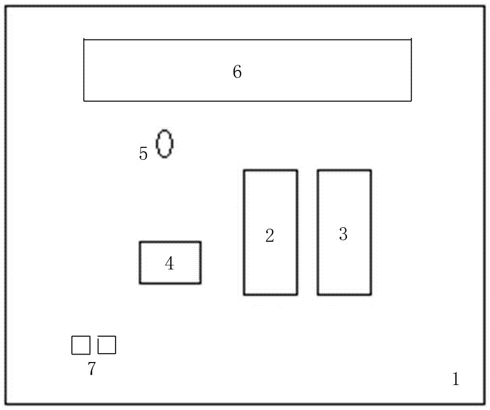
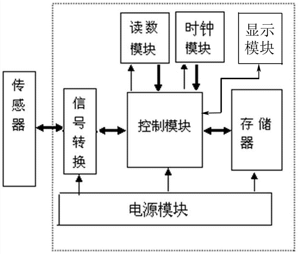
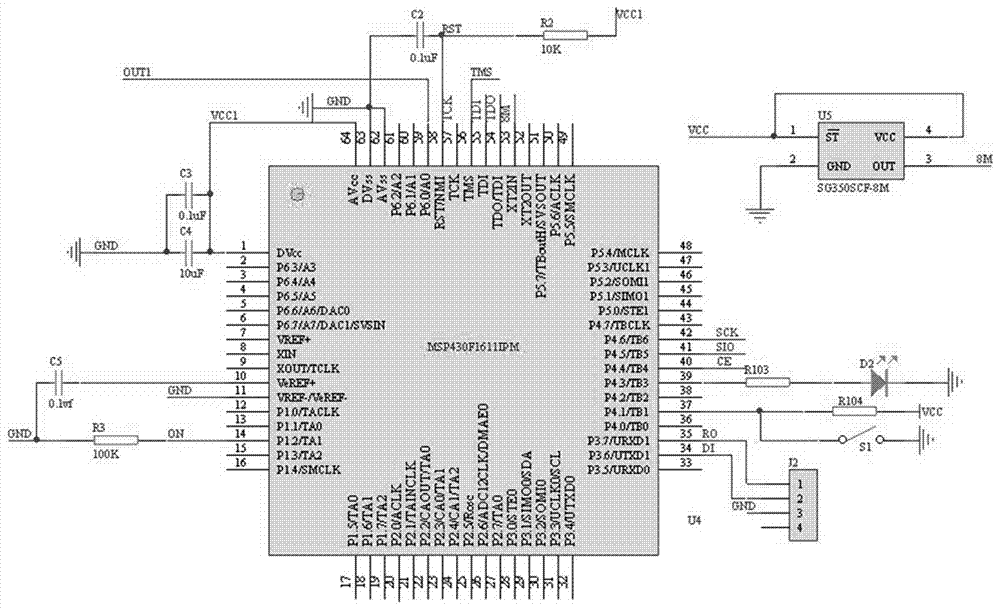
[0051] A low-voltage cable current test recorder, including a housing 1; as figure 1 As shown, the surface of the housing 1 is provided with a power button 2 , a start / stop button 3 , a USB interface 4 , a status indicator light 5 , a display screen 6 and a sensor interface 7 . The inside of the recorder is composed of current sensor, power conversion module, display module, control module, storage module, signal conversion module, reading module, clock module, etc. The system composition is as follows: figure 2 shown. The specific connection relationship is that the sensor interface 7 is connected to an AC current transformer; a control module is installed in the housing 1, and the control module is bidirectionally connected with a signal conversion module, a memory, a reading module and a clock module, and the signal conversion module Th...


PUM


Abstract

The invention discloses a low voltage cable current test recorder, including a casing (1). A power button (2), a start / stop button (3), a USB interface (4) and a sensor interface (7) are arranged on the surface of the casing (1). The sensor interface (7) is connected with an AC current transformer. A control module is installed in the casing (1) and is bidirectionally connected with a signal conversion module, a memory, a reading module and a clock module. The input end of the signal conversion module is connected with the sensor interface (7) in the casing (1). Through the measurement, storage and analysis of the AC current of the power cable in the low-voltage power supply network, the low voltage cable current test recorder realizes the automatic identification and the corresponding function of the outgoing cable of the low-voltage side of the transformer and the user side cable. Through the measurement, storage and analysis of the AC current of the power cable in the low-voltage power supply network, the detection range of online loss detection can be narrowed.

Description

technical field [0001] The invention relates to a power system measurement tool, in particular to a hand-held low-voltage cable current test recorder. Background technique [0002] In the inspection of low-voltage power consumption of power companies, there is a problem that the relationship between transformers and users is unclear due to cable confusion. In the power distribution room, multiple outgoing cables of the transformer are laid into the ground, and the other outlets are laid in front of each building. Because it is impossible to observe the direction of the cable under the surface, it is impossible to judge which cable carries which users, resulting in the problem of unclear correspondence between transformers and users. The first makes the power supply company not know which users need to be notified in advance of the power outage when it is going to overhaul and outage a certain transformer. Second, when the power supply company assesses the line loss, it nee...

Claims


Application Information

Patent Timeline
Patent Type & Authority Applications(China)
IPC IPC(8): G01R19/25G01R15/18
CPCG01R19/2506G01R15/18G01R19/0092
Inventor 马永岗刘晶王静范若愚梁志剑张艳兵马煜坤葛令源
Owner STATE GRID CORP OF CHINA
Learn More