
Clamping device for bolt locking

A clamping device and screw technology, used in metal processing, metal processing equipment, manufacturing tools, etc., can solve the problem of easy deviation of screws, reduce the probability of deviation, ensure smooth completion, and improve stability.

Pending Publication Date: 2017-10-20
深圳市威富智能设备有限公司
View PDF0 Cites 2 Cited by
  • Summary
  • Abstract
  • Description
  • Claims
  • Application Information

AI Technical Summary

Problems solved by technology

[0004] Aiming at the deficiencies of the prior art, the present invention provides a clamping device for screw locking to solve the shortcoming that the screw is easy to shift during screw locking

Method used


Image

  • Clamping device for bolt locking
  • Clamping device for bolt locking
  • Clamping device for bolt locking

Examples


Embodiment

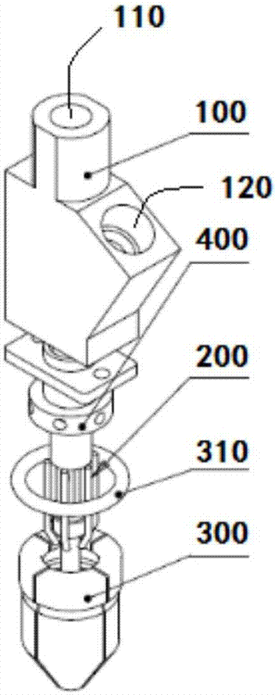
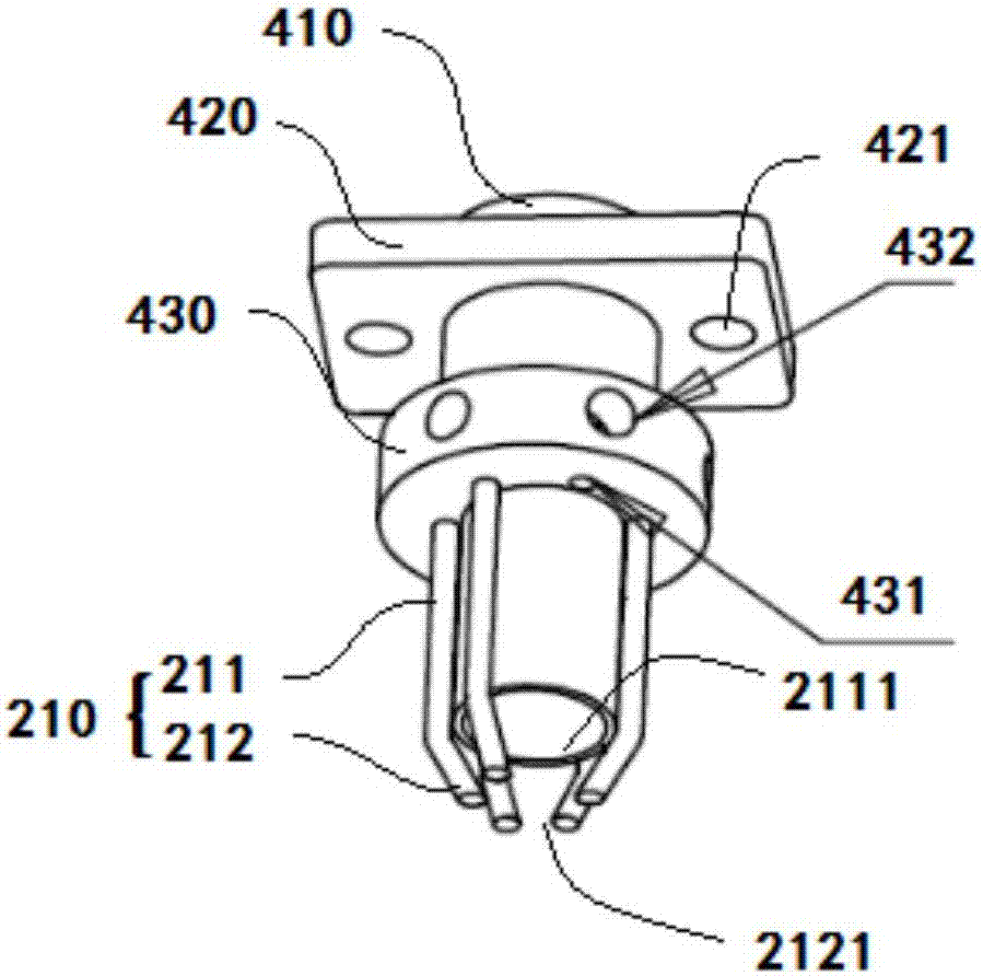
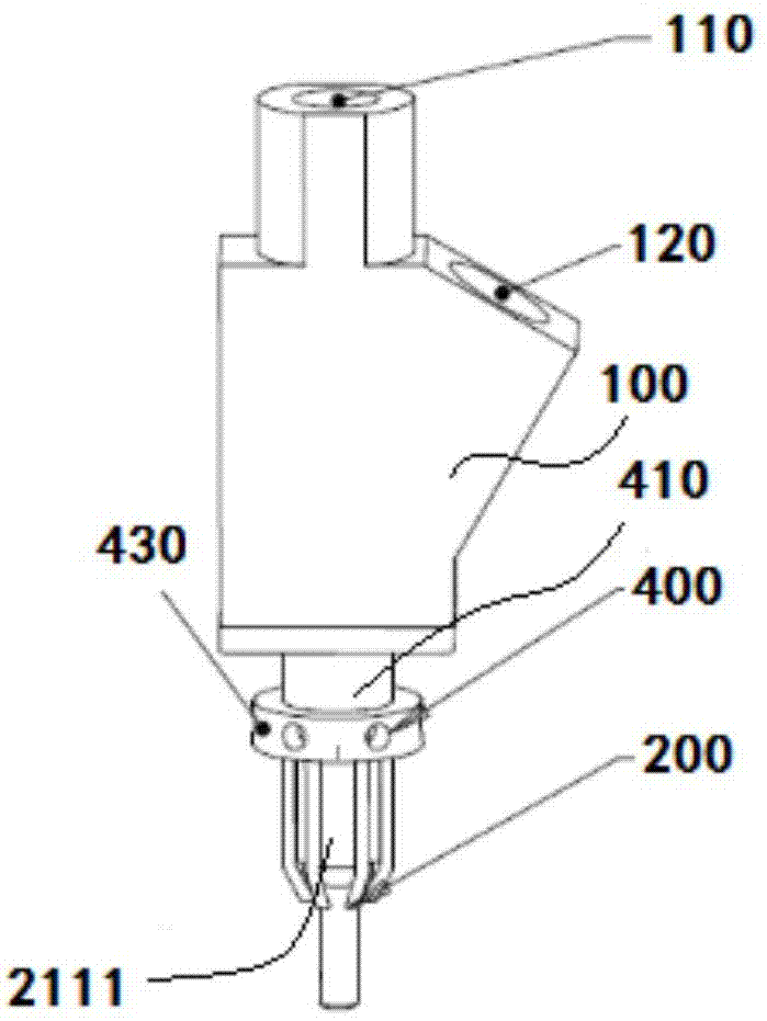
[0034] This embodiment provides a clamping device for screw locking, please refer to figure 1 , the clamping device for screw locking includes a base 100 , an inner clamping structure 200 and an outer clamping structure 300 .

[0035] Wherein, the inner clamping structure 200 is used to clamp the outer circumference of the screw, and the inner clamping structure 300 is connected to the base 100 . The outer layer clamping structure 300 is used to clamp the outer circumference of the screw, the outer layer clamping structure 300 is coaxially arranged with the inner layer clamping structure 200 and sleeved on the outer circumference of the inner layer clamping structure 200, the outer layer clamping structure 300 The bottom is lower than the bottom of the inner clamping structure 200 .

[0036] In this way, due to the existence of the inner layer clamping structure 200 and the outer layer clamping structure 300, and the outer layer clamping structure 300 is coaxially arranged wi...


PUM


Abstract

The invention discloses a clamping device for bolt locking. The clamping device comprises a base, an inner clamping structure and an outer clamping structure. The inner clamping structure is used for clamping the periphery of a bolt and connected with the base. The outer clamping structure is used for clamping the periphery of the bolt. The outer clamping structure and the inner clamping structure are arranged coaxially, and the outer clamping structure is arranged at the periphery of inner clamping structure in a sleeving mode. The bottom of the outer clamping structure is lower than the bottom of the inner clamping structure. According to the clamping device for the bolt locking, the stability of the bolt during the bolt locking can be improved, so that the probability of disorientation of the bolt in the locking process can be reduced well, and the fact that locking movement is completed successfully is ensured.

Description

technical field [0001] The invention relates to the technical field of screw locking, in particular to a clamping device for screw locking. Background technique [0002] At present, most screw locks are realized by means of an automatic screw locking machine, and the screw is locked at the corresponding position through the automatic locking screw machine. The automatic screw locking machine can well replace the manual work of screw locking, which greatly improves the working efficiency of screw locking, and can also guarantee the quality of screw locking to a certain extent. At present, the automatic locking screw machines on the market generally use a single-layer 2-petal or 4-petal lotus beak. Although the structure of the single-layer lotus beak is simple, the screw is easy to shift when the nail is pulled out. For screws with a slightly longer length In other words, the offset phenomenon is more serious, and the reason is that the single-layer lotus beak has only one l...

Claims


Application Information

Patent Timeline
IPC IPC(8): B23P19/06
CPCB23P19/006B23P19/06
Inventor 张少林关航健王攀
Owner 深圳市威富智能设备有限公司
Learn More