
Automatic repair-grinding device for resistance spot-welding electrodes

A technology of resistance spot welding and dresser, which is applied in the direction of electrode characteristics, electrode maintenance, etc., can solve the problems of difficult to effectively control the excessive cutting of electrode materials, large edge impact, and strong edge impact, etc., to achieve the cost of use Low, grinding quality assurance, improve the effect of working life

Active Publication Date: 2017-10-20
天津市扬帆科技开发有限公司
View PDF10 Cites 4 Cited by
  • Summary
  • Abstract
  • Description
  • Claims
  • Application Information

AI Technical Summary

Problems solved by technology

[0005] (2) Various negative attributes of the known technology automatic electrode dresser due to its common working principle: First, the cutting tool rotates on the fixed plane with the axis of the electrode as the axis; The theoretical trajectory line of the working surface processing has a helix angle, which cannot guarantee the parallelism between the two electrode surfaces after grinding and the workpiece surface; second, in order to reduce the adverse effect of dynamic load on the impact of the cutting edge, most of the electrode pressure The working mode that the cutting edge starts to rotate after the stable establishment on the cutting edge, that is, the cutting edge is carried and started under the action of a large electrode pressure and the speed increases from zero to the maximum working speed instantaneously, which has a great impact on the cutting edge; the third , from the outer diameter of the electrode to the axis of the electrode, the cutting linear velocity of the cutting edge has a change from V=Vmax to V=0, that is, the cutting acceleration and cutting linear velocity at the outer diameter of the electrode are the largest, and the impact on the cutting edge Strongest; within a certain radius from the electrode axis, because the cutting line speed is less than the critical cutting speed, there is no cutting effect on the electrode surface. The comprehensive result of the tearing superposition effect has a certain negative impact on the uniformity and conductivity of the electrode material on the electrode surface and the life of the cutting edge; Fourth, in order to remove the metal to be cut at the axis of the electrode, considering the inevitable existence of the electrode Due to factors such as repeated positioning accuracy errors and the necessary fit clearance for cutting tool rotation, the length of the cutting edge must pass through the axis in the design, and the local cutting edge beyond the axis is subjected to harsh conditions such as reverse edge cutting and hard extrusion during the cutting process. The working life of the mouth is extremely unfavorable; Fifth, the accuracy of repeated positioning errors will cause the offset of the pressure center, and the offset of the pressure center will make the best use of the matching gap to make the electrode grinding surface form a certain processing deflection angle relative to the workpiece surface, which intensifies the electrode work. The non-parallelism between the surface and the surface of the workpiece will adversely affect the relative stability of the electrode feed cross-sectional area and the quality of the solder joints.
[0006] (3) The cutting force is established by using the electrode pressure and the cutting edge speed. The amount of grinding is determined by the relationship between the electrode pressure, the cutting edge speed and the grinding time, rather than the distance between the electrode surface to be repaired and the cutting edge during grinding. It is difficult to effectively control the excessive cutting of electrode materials by controlling the relative displacement between them
[0007] (4) Only suitable for electrode grinding of linear motion welding tongs in robot welding tongs

Method used


Image

  • Automatic repair-grinding device for resistance spot-welding electrodes
  • Automatic repair-grinding device for resistance spot-welding electrodes
  • Automatic repair-grinding device for resistance spot-welding electrodes

Examples


Embodiment Construction

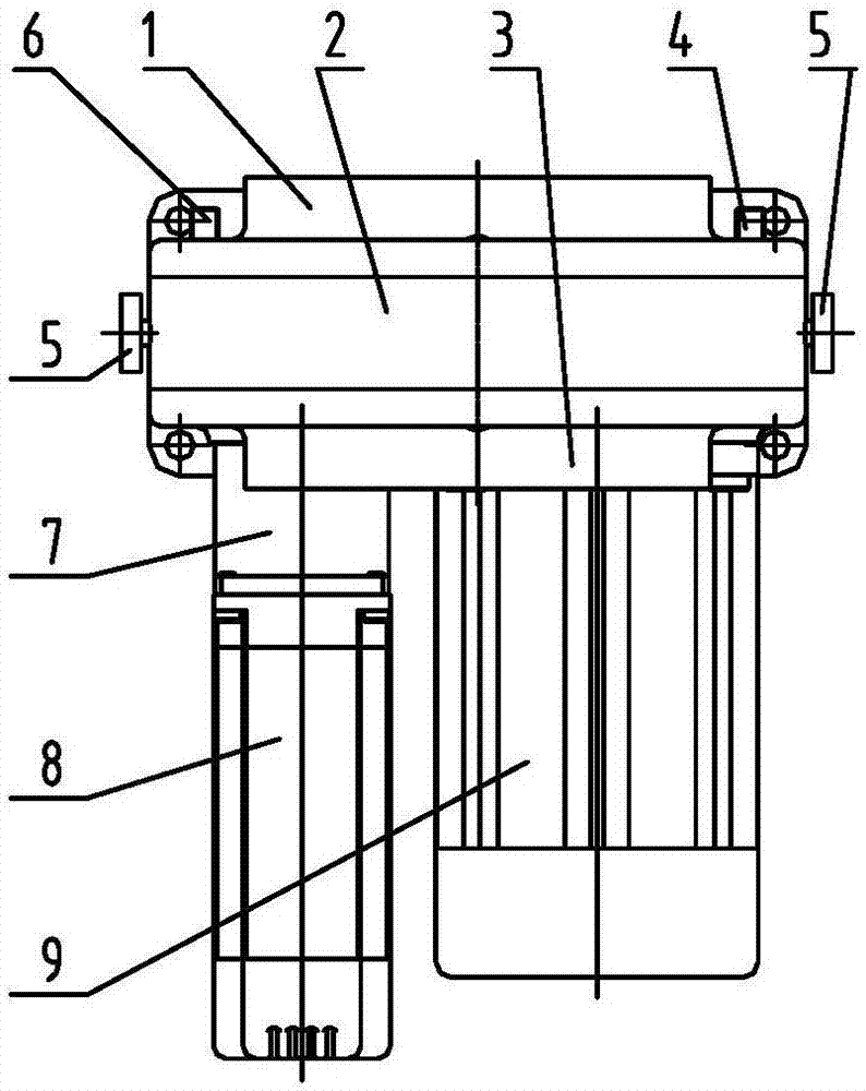
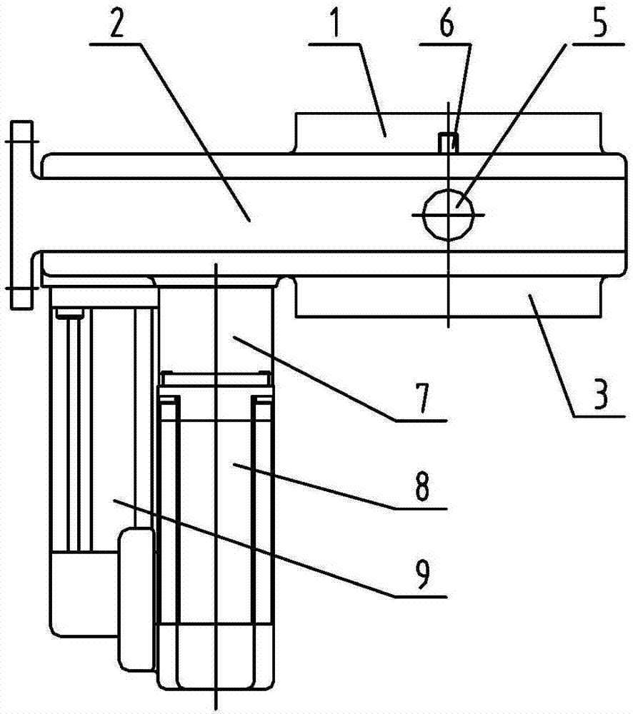
[0074] The invention relates to a grinder specially used for automatic grinding of linear moving electrodes, electrodes including automatic welding tongs, manual welding tongs and fixed spot welding machines in the spot welding process. The electrode automatic grinder of the present invention realizes the precise control of the electrode grinding amount through the cutting mode controlled by the micro cutting amount and the positioning displacement in the electrode grinding process; The knife amount is determined by the displacement speed of the electrode surface to be repaired towards the cutting edge, and the displacement speed of the electrode to be repaired surface to the cutting edge is always controlled by the preset program in the dresser during the electrode grinding process. When the cutting tool grinds the electrode, it works in the form of revolution + rotation. The rotation axis of the revolution takes the electrode axis as the axis, that is, the connection line betwe...


PUM


Abstract

The invention discloses an automatic repair-grinding device for resistance spot-welding electrodes. The automatic repair-grinding device comprises a main frame body, a cutting system, a cutting displacement moving system and a positioning reference adjusting mechanism; the cutting system comprises a rotating power input gear, a first transition gear and a tool rest which are driven by a rotating power alternating current motor sequentially; the tool rest carries combined cutting tools; the cutting displacement moving system comprises a speed reducer, a power input gear and a second transition gear which are driven by a servo motor sequentially; the second transition gear meshes with the power input gear; the second transition gear and a third transition gear which are assembled coaxially and adopt identical structures mesh with circular cam gear rings on two sides respectively and interact with cam discs on the two sides respectively through cam slopes; with the positioning reference adjusting mechanism, the positioning reference is adjusted through adjustment of the position relationships of two independent gear shafts and two sliding sleeve gears and the upper and lower cam discs. Through the micro-cutting-quantity fixed-displacement cutting and repair-grinding manner, the device can have the remarkable positive effects in the aspects of the product spot-welding quality, the spot-welding technology cost and the like during spot-welding production.

Description

technical field [0001] The present invention relates to the special process equipment for welding electrode grinding in the resistance spot welding process, more specifically, the present invention relates to the electrode grinding process specially used for linear motion welding tongs or fixed spot welding machines in the resistance spot welding process. Self-sharpening grinder. Background technique [0002] During the continuous spot welding process, under the cyclic effect of high temperature and high pressure and other harsh workloads, the diameter and composition of the electrode working surface, the contact area between the electrode surface and the workpiece surface, contact resistance and contact thermal resistance, etc. The increase is constantly changing, and a series of changes dynamically change the total resistance value between the spot welding joints and the resistance distribution ratio relationship along the thickness direction, and the resistance heat gener...

Claims


Application Information

Patent Timeline
Patent Type & Authority Applications(China)
IPC IPC(8): B23K11/30
CPCB23K11/3063
Inventor 顾扬顾啸熊佩军刘为民邵东辉李治王义兵顾寅陈林李耀白雪峰
Owner 天津市扬帆科技开发有限公司
Learn More