
Stirring device easy to feed during operation

A stirring device and operation process technology, applied to mixers with rotating stirring devices, transportation and packaging, mixer accessories, etc., can solve the problem of slowness, inability to accurately control the content of ingredients, and easy to fall to the non-stop rotating stirring claws problems such as above, to achieve the effect of improving efficiency and accurate control

Pending Publication Date: 2017-10-20
VEEGOO TECH CO LTD
View PDF14 Cites 3 Cited by
  • Summary
  • Abstract
  • Description
  • Claims
  • Application Information

AI Technical Summary

Problems solved by technology

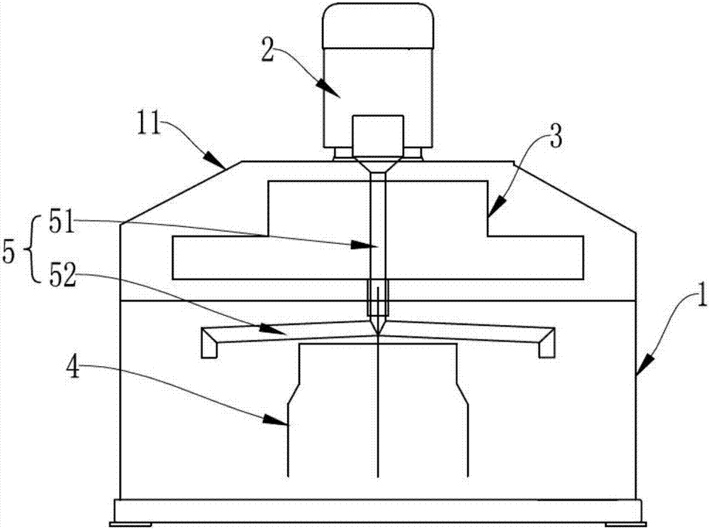
[0003] The composition of artificial stone is various, the composition is different, and the timing of adding it to the initial mixture for uniform stirring is also different. In the mixer that uniformly mixes the materials within the scope of the prior art, the stirring claws of the mixer are stirring while going to the mixer. When adding materials in the mixing chamber, the newly added materials tend to fall on the top of the constantly rotating stirring claws, and this part of the materials will be continuously and slowly added to the mixing chamber during the continuous movement of the stirring claws. In particular, it falls on the homogeneously mixed materials in the later stage to affect the uniformity of the ingredients of the final mixture, so that it is impossible to accurately control the content of the corresponding ingredients in the product.

Method used


Image

  • Stirring device easy to feed during operation
  • Stirring device easy to feed during operation
  • Stirring device easy to feed during operation

Examples


Embodiment Construction

[0030] The technical solutions of the present invention will be further described below in conjunction with the accompanying drawings and through specific implementation methods.

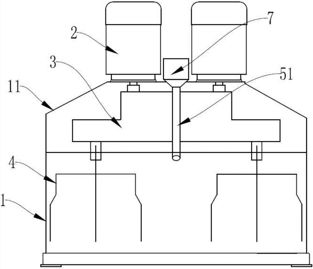
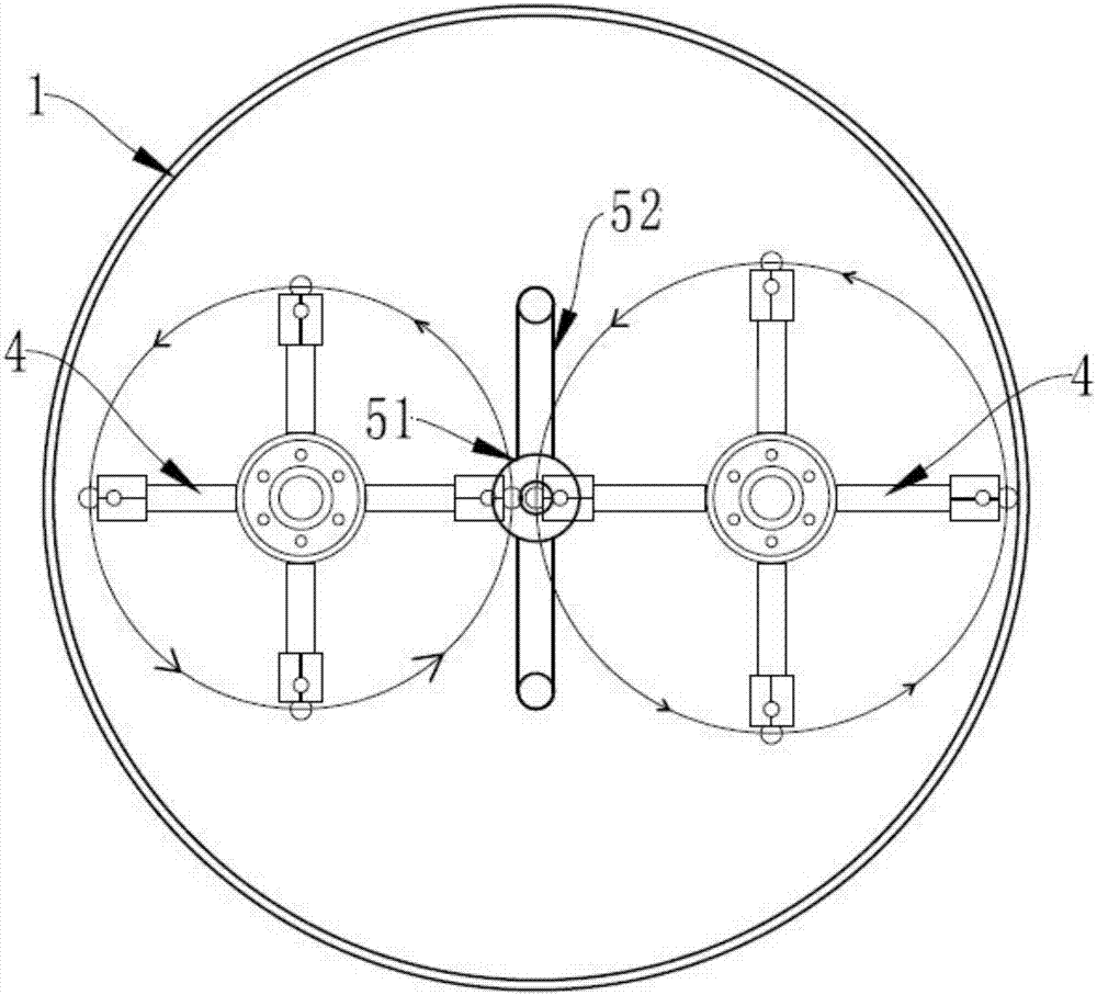
[0031] Such as figure 1 , figure 2 and image 3 As shown, a stirring device that facilitates feeding during operation; includes a mixing chamber 1, a driving device 2, a revolving transmission member 3, a stirring claw 4 and a feeding assembly 5, and the driving device 2 is installed on the mixing chamber. Cavity 1;

[0032] The stirring claw 4 is arranged on the revolution transmission part 3, the driving device 2 drives the revolution transmission part 3 to rotate, and the stirring claw 4 stirs the material in the mixing chamber 1;

[0033] The feed assembly 5 includes a main feed channel 51 and one or more feed branch channels 52;

[0034] The main feed channel 51 passes through the middle of the revolution transmission member 3 and can rotate synchronously with the revolution transmission m...


PUM


Abstract

The invention discloses a stirring device easy to feed during operation. The stirring device comprises a mixing chamber, drive units, a revolution transmission part, a stirring claw and a feed component; the feed component comprises a general feed channel and one or more than one feed branch channels; the general feed channel penetrates the middle of the revolution transmission part to rotate synchronously with the revolution transmission part, a feed inlet communicated with the outer world is arranged in the upper end of the revolution transmission part while the lower end is communicated with the feed branch channel, and discharge holes arranged in the feed branch channel discharge materials to the mixing chamber; the feed branch channel and the stirring claw are located on the same side of the revolution transmission part, the arc of the feed branch channel extends radially along rotation of the revolution transmission part, and the position of the feed branch channel is not coincided with the mounting position of the stirring claw. By the arrangement, the problem that the materials accumulated in the feed branch channel are difficult to clean up due to long-term use of the device is solved, feed efficiency is improved, and the content of the corresponding materials in the product is further accurately controlled.

Description

technical field [0001] The invention relates to a stirring device in the artificial stone field, in particular to a stirring device which facilitates material feeding during operation. Background technique [0002] Artificial stone usually refers to artificial stone solid surface material, artificial quartz stone, artificial stone granite, etc. Different types of artificial stone have different components, and all kinds of artificial stone are made of various original powder materials. It can be formed after the process of mixing, pressing, curing and other processes. [0003] The composition of artificial stone is various, and the timing of adding it to the initial mixture for uniform mixing is also different. In the mixer that uniformly mixes the materials within the scope of the prior art, the stirring claws of the mixer are stirring while going to the mixer. When adding materials in the mixing chamber, the newly added materials tend to fall on the top of the constantly ...

Claims


Application Information

Patent Timeline
Patent Type & Authority Applications(China)
IPC IPC(8): B01F7/30B01F7/26B01F15/02B01F27/93
CPCB01F27/93B01F27/95B01F35/2213B01F35/71705B01F35/71731B01F2101/28
Inventor 邱建平朱诗阳覃晓宇
Owner VEEGOO TECH CO LTD
Learn More