Phase discriminator and clock and data recovery circuit
A phase detector and circuit technology, applied in the direction of electrical components, automatic power control, etc., can solve the problem of high power consumption of CDR circuits, and achieve the effect of reducing power consumption and power consumption
- Summary
- Abstract
- Description
- Claims
- Application Information
AI Technical Summary
Problems solved by technology
Method used
Image

Examples
Embodiment 1
[0036]According to an embodiment of the present invention, an embodiment of a phase detector is provided. It should be noted that the steps shown in the flowcharts of the accompanying drawings can be executed in a computer system such as a set of computer-executable instructions, and, although in The flowcharts show a logical order, but in some cases the steps shown or described may be performed in an order different from that shown or described herein.
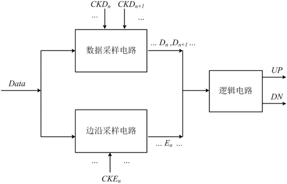
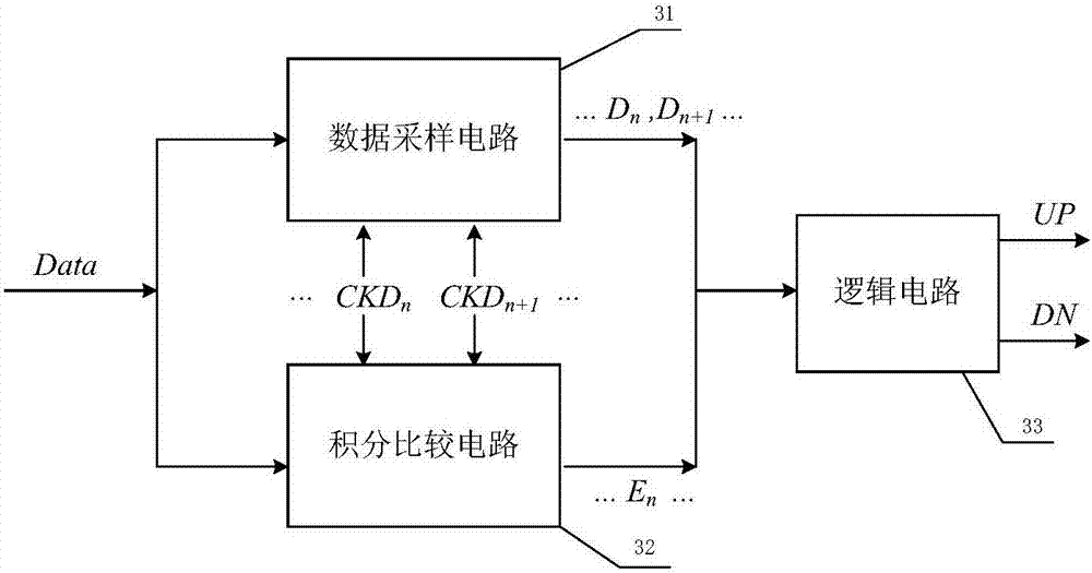
[0037] image 3 is a schematic structural diagram of a phase detector according to an embodiment of the present invention, such as image 3 As shown, the phase detector includes:
[0038] The data sampling circuit 31 is used to sample the baud rate of the data stream to obtain a data sampling sequence; the integral comparison circuit 32 is used to perform integral comparison on the data stream to obtain a quantized digital signal; the logic circuit 33 is used to obtain a quantized digital signal based on The data sampling s...
Embodiment 2
[0056] According to another aspect of the embodiments of the present invention, a clock and data recovery circuit is also provided, Figure 6 is a schematic structural diagram of a clock and data recovery circuit according to an embodiment of the present invention, such as Figure 6 As shown, the clock and data recovery circuit includes:
[0057] The input end of the phase detector 61 is used to receive the data stream; the output end of the phase detector 61 is connected with the input end of the charge pump 62, and the output end of the charge pump 62 is connected with the input end of the loop filter 63, and the loop filter The output terminal of the device 63 is connected with the input terminal of the voltage-controlled oscillator 64, wherein, the phase detector 61 obtains the data sampling sequence by performing baud rate sampling on the data stream; signal; output the corresponding level signal according to the parallel data sampling sequence and the quantized digital ...
PUM
 Abstract
Description
Claims
Application Information
 - R&D
- Intellectual Property
- Life Sciences
- Materials
- Tech Scout
- Unparalleled Data Quality
- Higher Quality Content
- 60% Fewer Hallucinations
Browse by: Latest US Patents, China's latest patents, Technical Efficacy Thesaurus, Application Domain, Technology Topic, Popular Technical Reports.
© 2025 PatSnap. All rights reserved.Legal|Privacy policy|Modern Slavery Act Transparency Statement|Sitemap|About US| Contact US: help@patsnap.com