
Coal sample while-drilling fixed point collecting device

A collection device and drilling-while-drilling technology, applied to sampling devices and other directions, can solve problems such as visual errors, large errors, and lack of authenticity, and achieve the effect of reducing exposure time

Pending Publication Date: 2017-10-03
河南霞光矿山设备有限公司
View PDF9 Cites 12 Cited by
  • Summary
  • Abstract
  • Description
  • Claims
  • Application Information

AI Technical Summary

Problems solved by technology

[0008] Combining the above problems, there are operational errors and visual errors in the collection process and results. The longer the exposure time, the greater the error, and the authenticity of the sample is not

Method used


Image

  • Coal sample while-drilling fixed point collecting device
  • Coal sample while-drilling fixed point collecting device
  • Coal sample while-drilling fixed point collecting device

Examples


Embodiment 1

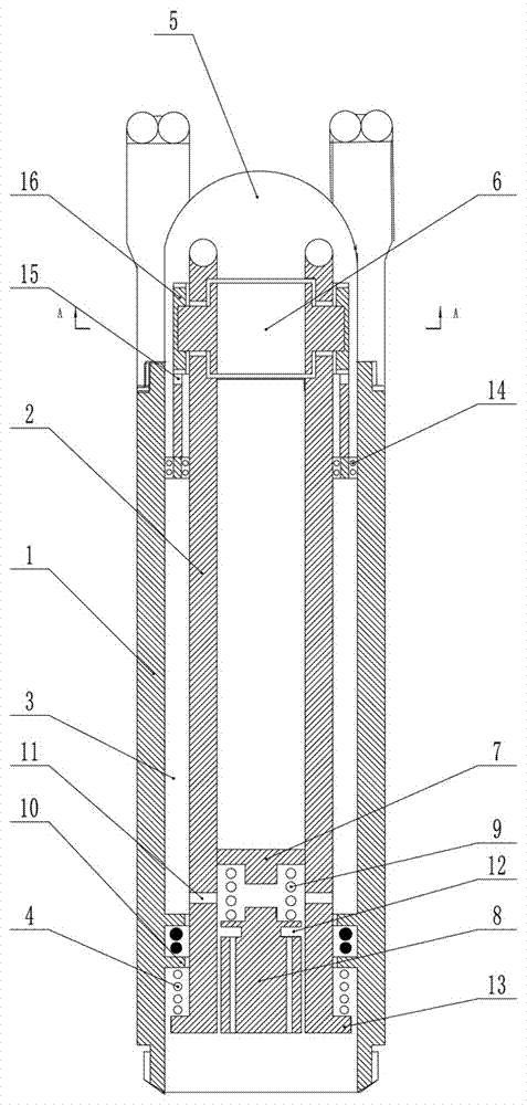
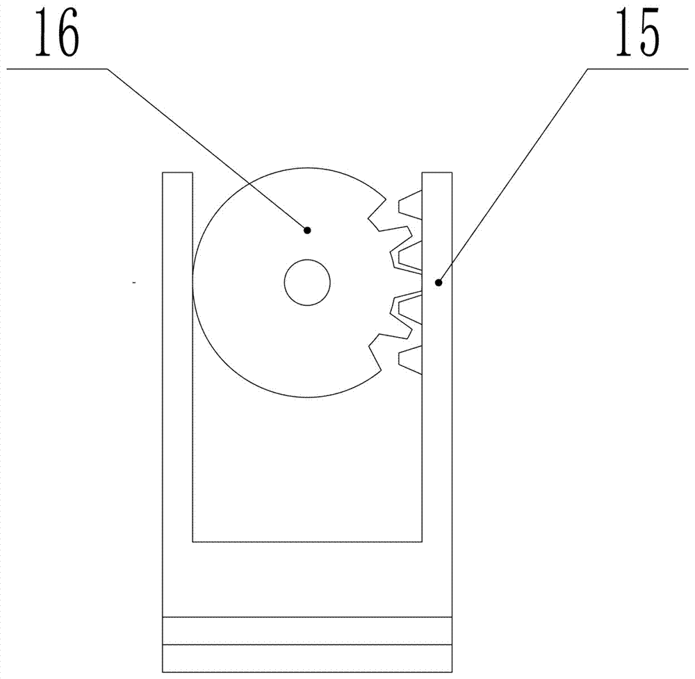
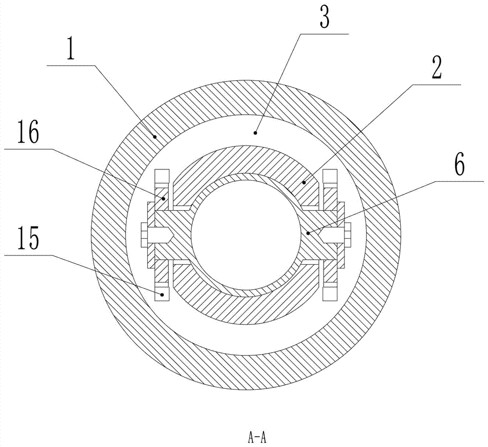
[0033] Such as Figure 1-Figure 3 As shown, a fixed-point collection device for coal samples while drilling includes a combined drill bit and a drill pipe. The drill pipe includes a cylindrical outer shell 1, a collection chamber 2 with only front openings, a pressure chamber 3, and a primary pressure valve. And secondary pressure spring 4.

[0034] The collection cavity 2 is coaxially arranged in the outer shell 1 and can reciprocate along the axial direction of the outer shell 1. The inner sides of the first and last ends of the outer shell 1 are provided with bosses 10, and the bosses 10 A sealing ring is installed inside, the collection cavity 2 is slidingly fitted with the sealing ring, a rib 13 is arranged at the tail end of the collection cavity 2, and the two ends of the secondary pressure spring 4 are respectively arranged in the collection cavity The rib 13 of 2 and the boss 10 at the tail end of the outer shell 1 form a high-pressure sealing structure at the tail e...

Embodiment 2

[0052] The difference between this embodiment and Embodiment 1 is that the pressure chamber is an independent structure, and the pressure chamber is located outside the outer casing or between the outer casing and the collection chamber, the purpose of which is to reduce the impact on The sealing requirements for the cooperation between the outer casing and the collection cavity require an additional completely sealed structure.

[0053] Further, the combined drill bit includes a drilling bit, the drilling bit includes a left half and a right half, the left half is hinged on the left side of the outer casing, and the right half is hinged on the The right side of the outer casing, the front end of the collection cavity is respectively hinged or abutted against the middle part of the front half and the middle part of the right half, and the left half and the middle part of the right half are docked to form the The drill bit described above has a two-petal structure. After openin...


PUM


Abstract

The invention provides a coal sample while-drilling fixed point collecting device. The device comprises a combined bit and a drill pipe, wherein the drill pipe comprises a tubular casing, a collection cavity with an opening formed only in the front end, a pressure cavity, a primary pressure valve and a secondary pressure spring; the collection cavity is coaxially arranged in the casing through the secondary pressure spring and can perform axial reciprocating motion along the casing; an opening of the collection cavity is sealed through a ball valve; the primary pressure valve bears is opened through pressure and then is communicated with the pressure cavity; the front end of the pressure cavity is sealed through a piston; the piston drives the ball valve to rotate through a transmission mechanism, so as to open and close the opening of the collection cavity; the combined bit adopts a detachable bit; a drilling bit is gradually opened through the thrust of the collection cavity during the process that the collection cavity moves forward relative to the casing. The coal sample while-drilling fixed point collecting device has the advantages of scientific design, fixed point sampling while drilling, timely sealing, short exposure time and high facticity.

Description

technical field [0001] The invention relates to a coal sample collection device, in particular to a coal sample fixed-point collection device while drilling. Background technique [0002] At present, various sampling methods are used for direct measurement of coal seam gas content in underground coal mines. The most common application is through normal cutting of drilling tools, drilling pipes or wind exhaust, and the operator receives coal powder at the hole opening for on-site interpretation. , and then sent to the gas content testing room for testing. [0003] This collection method has the following disadvantages: 1. The coal sample collected is subjected to multiple rolling by wind force and drill pipe, and the loss of gas is relatively large; 2. The position of the coal sample collected is Uncertain, or more adulteration; 3. The coal sample is exposed to the air for a long time and mixed with the air, which affects the authenticity of the coal sample. [0004] In ord...

Claims


Application Information

Patent Timeline
IPC IPC(8): G01N1/08
CPCG01N1/08
Inventor 张广江祝亚东周霞王坤
Owner 河南霞光矿山设备有限公司
Learn More