
Clamp structure

A fixture and clamping technology, which is applied in the field of fixture structure that is convenient for processing, can solve problems such as complicated operation, and achieve the effect of simple operation

Inactive Publication Date: 2017-10-03
SUZHOU MITAC PRECISION TECH
View PDF13 Cites 0 Cited by
  • Summary
  • Abstract
  • Description
  • Claims
  • Application Information

AI Technical Summary

Problems solved by technology

[0005] Therefore, the object of the present invention is to provide a fixture structure to solve the problem that the existing electrodes need to calibrate the processing plane operation and the operation is complicated when the second processing at a different angle from the first processing is performed after the existing electrode is processed once.

Method used


Image

  • Clamp structure
  • Clamp structure
  • Clamp structure

Examples


Embodiment Construction

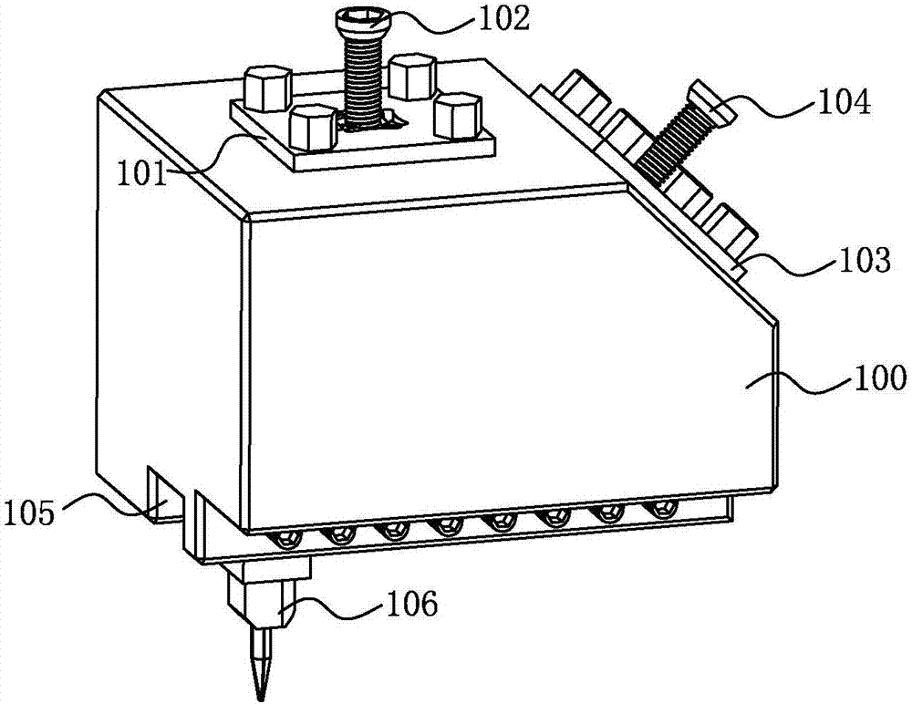
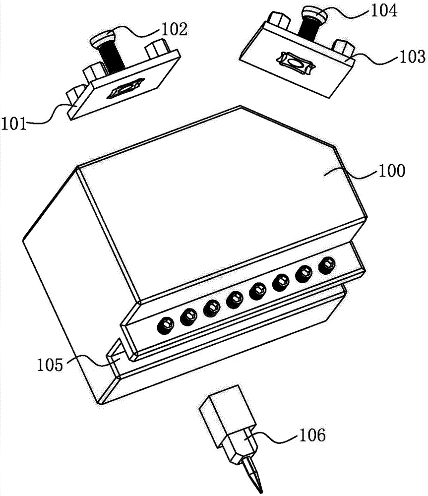
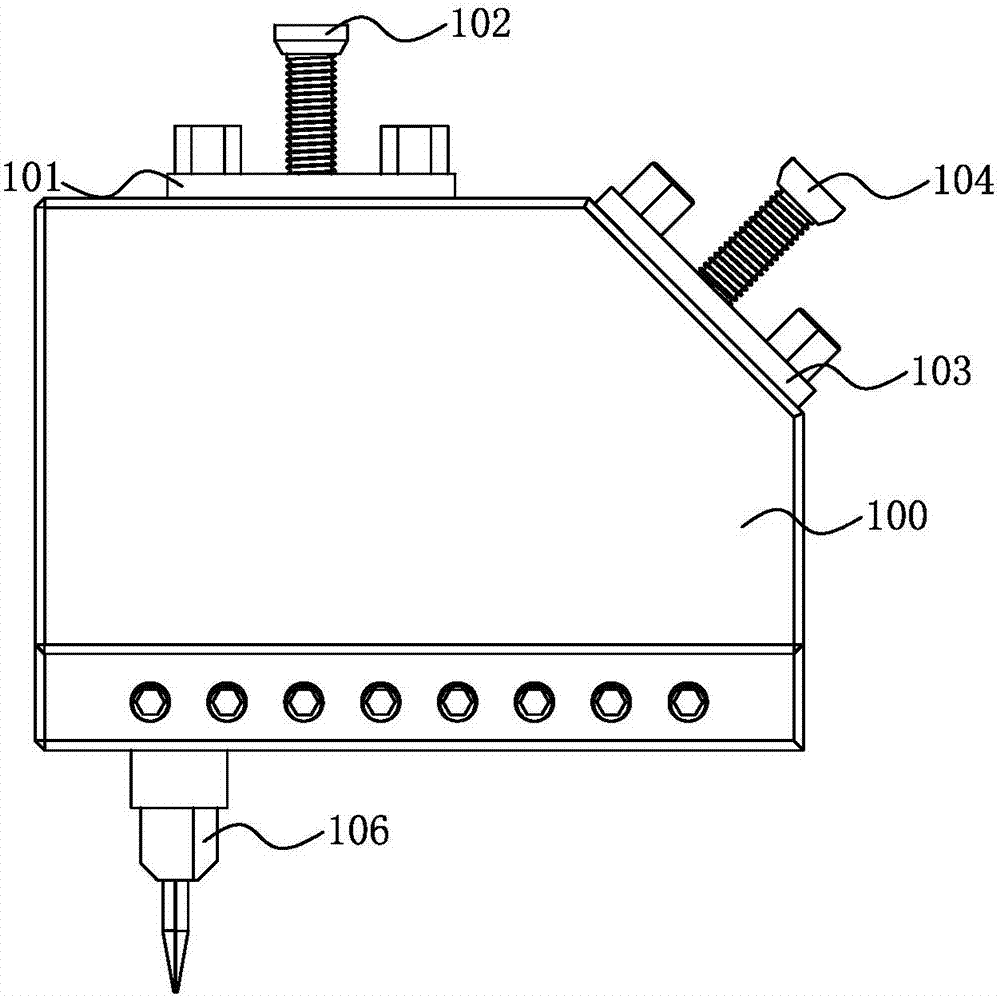
[0017] see figure 1 , 2 , figure 1 Illustrated as a schematic diagram of the assembly structure of a preferred embodiment of a fixture structure of the present invention, figure 2 It is a schematic diagram showing an exploded structure of a preferred embodiment of a fixture structure of the present invention.

[0018] In order to achieve the above object, the fixture structure provided by the present invention includes:

[0019] The fixture base 100 has a first plane, a second plane and a third plane on it, the first plane is parallel to the third plane, there is an angle between the first plane and the second plane, and the first plane is parallel to the third plane. The angle between the plane and the second plane is 135 degrees;

[0020] The first clamping part includes a first clamping gasket 101 and a first base screw 102, the first clamping gasket 101 is fixed on the first plane, and one end of the first base screw 102 is fixed on The other end of the first clampin...


PUM


Abstract

The present invention discloses a fixture structure, comprising: a fixture base with a first plane, a second plane and a third plane on it, the first plane is parallel to the third plane, and the distance between the first plane and the second plane is There is an included angle; the first clamping part includes a first clamping gasket and a first base screw, the first clamping gasket is fixed on the first plane, and one end of the first base screw is fixed The other end of the first clamping gasket is used to connect the air seat; the second clamping part includes the second clamping gasket and the second base screw, and the second clamping gasket is fixed on the On the second plane, one end of the second base screw is fixed to the second clamping gasket, and the other end is used to connect the air pressure seat; the clamping workpiece groove is located on the third plane, and the clamping workpiece groove Electrodes for processing are installed inside. When performing the second processing at a different angle from the first processing, there is no need to calibrate the processing plane, and the operation is simple.

Description

【Technical field】 [0001] The invention relates to a fixture structure, in particular to a fixture structure which is convenient for processing. 【Background technique】 [0002] CNC (Numerical Control Machine Tool) is the abbreviation of Computer numerical control machine tool (Computer numerical control), which is an automatic processing controlled by a program. EDM is also the abbreviation of Electrical Discharge Machining, that is, electric discharge machining. The basic working principle of EDM is to use a continuously moving thin metal wire (called electrode wire) as an electrode to perform pulse spark discharge on the workpiece to remove metal and cut into shape. [0003] Both CNC machining and EDM machining will use electrodes. After using the electrode for CNC machining, and then using the electrode for EDM discharge machining, for example, when performing EDM machining on the duckbill rubber joint of the workpiece, there is a need for a gap between the electrode and ...

Claims


Application Information

Patent Timeline
Patent Type & Authority Applications(China)
IPC IPC(8): B23H11/00
CPCB23H11/006B23H2500/00
Inventor 张亮
Owner SUZHOU MITAC PRECISION TECH
Learn More