
Multifunctional direct sowing machine

A live broadcast machine and multi-functional technology, applied in the field of live broadcast machine, can solve the problems of difficult operation, single function of the device, time-consuming and labor-intensive, etc., and achieve the effect of simple and convenient adjustment, strong practical performance and wide application range

Pending Publication Date: 2022-03-11
广州林电智能科技有限公司
View PDF5 Cites 0 Cited by
  • Summary
  • Abstract
  • Description
  • Claims
  • Application Information

AI Technical Summary

Problems solved by technology

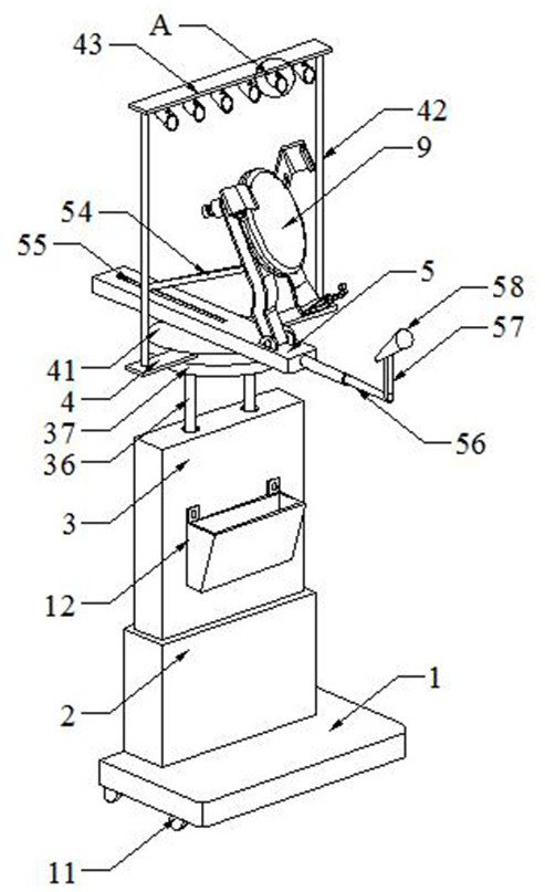
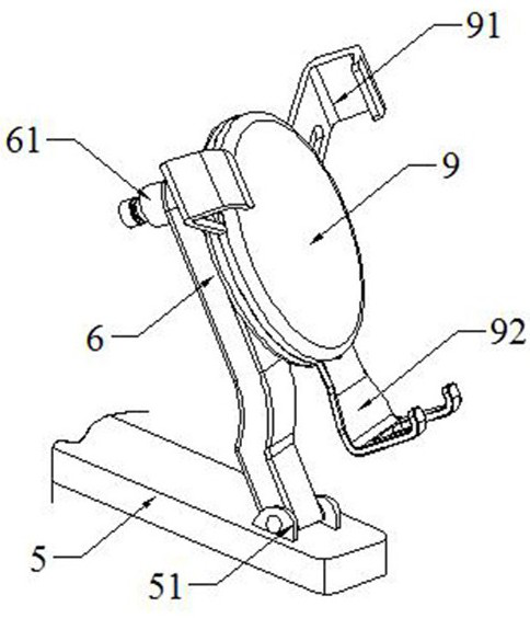
[0003] However, the structure and adjustment methods of the current interactive display equipment for live broadcasting are single, and there are few functions. Basically, only display is the function, and the height of the live broadcast machine cannot be adjusted, so that the live broadcast machine can meet users of different heights, or in different states. In addition, the angle of the mobile phone cannot be adjusted during the live broadcast, and the mobile phone cannot be adjusted to a certain angle, so as to meet the multi-directional and multi-angle live broadcast, and support the mobile phone Fixing is more complicated, difficult to operate, time-consuming and labor-intensive. In addition, lights and microphones are needed during the live broadcast process. The existing device has a single function and cannot be realized. For this, we propose a multi-functional live broadcast machine

Method used


Image

  • Multifunctional direct sowing machine
  • Multifunctional direct sowing machine
  • Multifunctional direct sowing machine

Examples


Embodiment Construction

[0023] The technical solutions in the embodiments of the present invention will be clearly and completely described below in conjunction with the accompanying drawings in the embodiments of the present invention. Obviously, the described embodiments are only some of the embodiments of the present invention, not all of them. Based on The embodiments of the present invention and all other embodiments obtained by persons of ordinary skill in the art without making creative efforts belong to the protection scope of the present invention.

[0024] In the description of the present invention, it should be noted that the terms "top", "bottom", "one side", "another side", "front", "rear", "middle part", "inner", " The orientation or positional relationship indicated by "top", "bottom", etc. is based on the orientation or positional relationship shown in the drawings, which is only for the convenience of describing the present invention and simplifying the description, rather than indic...


PUM


Abstract

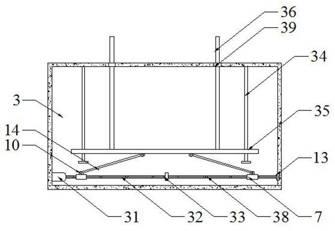
The invention relates to a multifunctional direct seeding machine which comprises a base plate, a base frame, a lifting frame, a rotating plate, a fixing frame and an arc-shaped supporting rod and is characterized in that the base frame is fixedly welded to one end of the top of the base plate, the lifting frame is fixedly welded to the center of the top of the base frame, and a first motor is fixedly welded to the center of one side of the bottom end in the lifting frame; a rotating rod is fixedly welded to the output end of the first motor, a limiting plate is fixedly welded to the position, located at the middle end in the lifting frame, of the rotating rod, movable blocks are movably connected to the positions, located on the two sides of the limiting plate, of the rotating rod, T-shaped limiting rods are fixedly welded to the two ends of the top in the lifting frame, and movable plates are movably connected to the T-shaped limiting rods in a penetrating mode. The mobile phone base frame has the beneficial effects that the height of the mobile phone base frame is adjusted through a first motor, a rotating rod, a movable block, a hinge rod, a movable plate and a movable rod in the lifting frame, the angle of an arc-shaped supporting rod on a rotating seat is adjusted through a second motor, a lead screw and the movable block in the fixing frame, adjustment is easy and convenient, and the practicability is high.

Description

technical field [0001] The present invention relates to the technical field related to live broadcasting machines, in particular to a multifunctional live broadcasting machine. Background technique [0002] With the development of Internet technology, the concept of live broadcasting has been expanded and developed. More people pay attention to live broadcasting, especially the ecological chain of live video broadcasting. Through network signals, online watching sports events (ball games, etc.) and Other major events and news, etc. In this way, the public has a broad and free choice. In recent days, webcasts have sprung up like bamboo shoots after rain. Live broadcasts are closely related to everyone. Currently, only a smart phone is needed to achieve live broadcasts. , make life more exciting. [0003] However, the structure and adjustment methods of the current interactive display equipment for live broadcasting are single, and there are few functions. Basically, only dis...

Claims


Application Information

Patent Timeline
Patent Type & Authority Applications(China)
IPC IPC(8): A01C7/00F21V33/00
CPCA01C7/00F21V33/00Y02P60/00Y02P60/20
Inventor 陈林
Owner 广州林电智能科技有限公司
Learn More