
Steel structure lifting device

A lifting device, steel structure technology, applied in cranes, transportation and packaging, load hanging components, etc., can solve problems such as trouble, waste of time, etc., and achieve the effect of improving work efficiency

Inactive Publication Date: 2018-12-18
江苏杰瑞钢结构有限公司
View PDF8 Cites 0 Cited by
  • Summary
  • Abstract
  • Description
  • Claims
  • Application Information

AI Technical Summary

Problems solved by technology

[0002] Lifting devices are usually used when building a steel structure skeleton, so that the required steel structure can be quickly and safely transported to the desired location, but the current steel structure lifting device only lifts the steel structure to the required height, and cannot Changing the angle of the hoisted steel structure, and then the workers manually turn it to a suitable position for installation, which is a waste of time and effort, which is very troublesome

Method used


Image

  • Steel structure lifting device

Examples


Embodiment Construction

[0010] In order to make the object, technical solution and advantages of the present invention clearer, the present invention will be further described in detail below through the accompanying drawings and embodiments. However, it should be understood that the specific embodiments described here are only used to explain the present invention, and are not intended to limit the scope of the present invention.

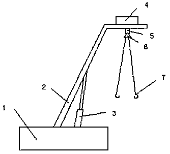
[0011] Such as figure 1 As shown, a kind of steel structure lifting device that the present invention adopts comprises lifting device body 1, lifting rod 2 and hydraulic device 3, and described lifting device body 1 is provided with lifting rod 2, and described lifting device body 1 and A hydraulic device 3 is arranged between the lifting rods 2, and the upper end of the lifting rod 2 is provided with a rotary motor 4, and the rotary motor 4 is rotatably provided with a rotating shaft 5, and the rotating shaft 5 is provided with a lifting ring 6, The suspension ring 6 is...


PUM


Abstract

The invention discloses a steel structure lifting device which comprises a lifting device body, a lifting rod and a hydraulic device. The lifting rod is arranged on the lifting device body. The hydraulic device is arranged between the lifting device body and the lifting rod. A rotating motor is arranged at the upper end of the lifting rod, a rotating shaft is rotatably arranged below the rotatingmotor, a lifting ring is arranged on the rotating shaft, and one or more lifting ropes are arranged on the lifting ring. The angle of a lifted steel structure can be changed, thus the lifted steel structure reaches the required position, the time and labor are saved, and the working efficiency is improved.

Description

technical field [0001] The invention relates to a lifting device, in particular to a steel structure lifting device. Background technique [0002] Lifting devices are usually used when building a steel structure skeleton, so that the required steel structure can be quickly and safely transported to the desired location, but the current steel structure lifting device only lifts the steel structure to the required height, and cannot Changing the angle of the steel structure being hoisted, and then the workers manually turn it to a suitable position for installation, which is a waste of time and effort, and is very troublesome. Contents of the invention [0003] Aiming at the above-mentioned problems in the prior art, the present invention provides a lifting device for a steel structure, which can change the angle of the lifted steel structure so as to reach the desired position, save time and effort, and improve work efficiency. [0004] In order to achieve the above object...

Claims


Application Information

Patent Timeline
Patent Type & Authority Applications(China)
IPC IPC(8): B66C23/06B66C13/08
Inventor 杨红
Owner 江苏杰瑞钢结构有限公司
Learn More