


Quick Research
Generate reliable direction feasibility study reports for your R&D in just a few steps.

Technical Q&A
Discover and master advanced knowledge NOW. Basics, ideas, possibilities, all at once.

Find Solutions
As an expert in R&D theories, this can generate solutions to your technical problems instantly.

Evaluate Feasibility
Analyze your overall solution with one click, know your potential R&D risks in advance.

Monitor Landscape
Get weekly tech updates, stay abreast of the latest tech innovations and key insights.
Fiber lens coupler and manufacturing method thereof
A fiber lens and coupler technology, applied in the field of optical communication, can solve the problems of high packaging cost and high technical difficulty, and achieve the effects of low packaging difficulty, easy coupling operation and low cost
- Summary
- Abstract
- Description
- Claims
- Application Information
AI Technical Summary
Problems solved by technology
Method used
Image

Examples
Embodiment
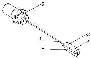
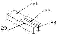
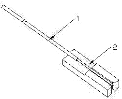
[0041] Example 1 see figure 1 . A fiber lens coupler, comprising a stepped cuboid substrate 2, the substrate 2 is made of transparent glass materials, such as quartz, borosilicate, single crystal silicon and the like. Such as figure 2 As shown, the substrate 2 is stepped, and the substrate 2 has an upper step 23 and a lower step 21. The central part of the step surface of the upper step 23 of the substrate 2 is provided with a V-shaped groove 22, and the groove 22 runs through the substrate front and rear. On the front and rear end surfaces of the upper step 23, the groove depth of the groove 22 is 0.16mm-0.18mm, and the included angle of the groove 22 is 88°-92°. A U-shaped groove 24 is provided on the front end surface of the groove 22, The U-shaped groove 24 is set on the front end surface of the substrate 2 and runs through the surface of the upper step 23 of the substrate and the bottom surface of the lower end of the substrate up and down. The width of the shaped gro...
Embodiment 2
[0055] see Figure 4 , Figure 5 , Figure 6 . The fiber lens coupler provided in this embodiment is different from Embodiment 1 in that in Embodiment 2, two V-shaped grooves 22 are arranged side by side on the center of the step surface of the step 23 on the substrate 2 of Embodiment 2, and the clip of the two grooves 22 The angles are 58°-62°, and the depth of the groove 22 is 0.17mm-0.20mm. The two V-shaped grooves run through the front and rear end faces of the upper step 23, and the two V-shaped grooves 22 A U-shaped groove 24 is provided on the end surface of the front-end substrate, and the groove width of the two grooves 22 is smaller than that of the U-shaped groove 24 . The cover plate 4 is arranged on the substrate 2 to cover the two V-shaped grooves 22, and an optical fiber lens 1 is placed in each groove 22, and each groove 22 is filled with an adhesive to connect the optical fiber lens 1 with the The base plate 2 and the cover plate 4 are fixed together, the ...
Embodiment 3
[0072] see Figure 7 , Figure 8 , Figure 9 .
[0073] The fiber lens coupler provided in this embodiment is different from Embodiment 2 in that 12 V-shaped grooves 22 are arranged side by side on the step surface of the upper step 23 of the substrate 2 of Embodiment 3, and the 12 grooves are adjacent to each other in sequence. . The cover plate 4 is set on the upper step 23 of the base plate 2 to cover the 12 grooves 22, and a fiber optic lens 1 is placed in each groove 22, and the 12 fiber optic lenses are adjacent to each other and correspond to the 12 grooves one by one. . The lens end of the fiber optic lens in this embodiment is a spherical lens, and each groove 22 is filled with adhesive to fix each fiber lens with the base plate 2 and the cover plate 4 as a whole. The lens ends of the 12 fiber lenses are in a U-shaped The grooves 24 are in a suspended state, and the lens ends of the 12 fiber lenses are aligned with each other. The pigtails of the 12 fiber optic ...
PUM
 Abstract
Description
Claims
Application Information
 - R&D Engineer
- R&D Manager
- IP Professional
- Industry Leading Data Capabilities
- Powerful AI technology
- Patent DNA Extraction
Browse by: Latest US Patents, China's latest patents, Technical Efficacy Thesaurus, Application Domain, Technology Topic, Popular Technical Reports.
© 2024 PatSnap. All rights reserved.Legal|Privacy policy|Modern Slavery Act Transparency Statement|Sitemap|About US| Contact US: help@patsnap.com