
Solar photovoltaic heat pump dryer

A solar photovoltaic and dryer technology, applied in dryers, drying, heat pumps, etc., can solve the problems of high-power operation damage, high maintenance costs, waste of energy, etc., to reduce maintenance costs and use costs, and ensure safety. Stable operation, reducing the effect of high-power operation

Inactive Publication Date: 2017-09-29
GUANGXI JIKUAN SOLAR ENERGY EQUIP
View PDF0 Cites 2 Cited by
  • Summary
  • Abstract
  • Description
  • Claims
  • Application Information

AI Technical Summary

Problems solved by technology

[0002] As a non-polluting and clean energy, solar energy is widely used in various fields. For example, using solar energy to dry objects, because the temperature required for drying objects is relatively high, most of the existing drying equipment uses mains power supply, which not only wastes energy , and it also pollutes the environment to a certain extent. Although solar drying equipment appears on the market, it converts solar energy into electrical energy and stores it in the battery, so that a set of equipment requires many battery packs, which further leads to large equipment. The cost is high, and maintenance is inconvenient, and the maintenance cost is high. In addition, heat pumps are also used to dry objects, but heat pumps absorb the low-temperature heat of the air and convert it to high temperature through the compressor. Because of its low temperature, it takes a lot of time to convert it to a high-temperature compressor. High-power operation not only requires more electric energy but also damages equipment due to long-term high-power operation of the compressor. Therefore, an equipment that comprehensively utilizes solar energy and heat pumps needs to be developed.

Method used


Image

  • Solar photovoltaic heat pump dryer
  • Solar photovoltaic heat pump dryer

Examples


Embodiment

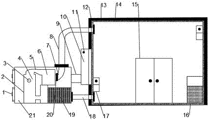
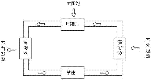
[0019] see figure 1 and figure 2 The present invention provides a solar photovoltaic heat pump dryer, which includes a box body 1 and an air-drying box 6. Since the box body 1 is made of transparent plastic, external sunlight can directly shine on the inside of the box body 1, thereby making the box body 1 The interior can heat up quickly, and the interior of the box body 1 is relatively sealed, so that the heat inside the box body 1 will not be lost, and then keep warm to ensure the heating of the equipment. There is a control box 2 on the left side of the box body 1, and the A single-chip microcomputer 19 is arranged in the box 2, a photovoltaic module 3 is arranged on the top of the box body 1, and a sliding door 11 is arranged on the front of the box body 1 at the same time, and an auxiliary heat pipe 13 and a heat pump unit 15 are arranged in the sliding door 11, and the auxiliary The heat pipe 13 is located on the left side inside the box body 1, and the heat pump unit...


PUM


Abstract

The invention discloses a solar photovoltaic heat pump dryer, which comprises a box body and an air-drying box. Four photovoltaic modules are arranged on the top of the box body, and a control box is arranged on the left side of the box body. There is a sliding door on the front, and a radiant heat pipe is arranged inside the door, a heat pump unit is arranged on the right side of the radiant heat pipe, and six battery boxes are arranged on the upper part of the heat pump unit; Air outlet, and an air outlet is provided on the right side of the air-drying box, and a temperature sensor is installed on the upper surface of the air outlet, and a heat dissipation pipe is provided inside the air-drying box. Since the photovoltaic module can provide power, the set The auxiliary heat pipe can provide auxiliary heat for the heat pump unit. At this time, the heat pump unit raises the heat and transports it to the heat dissipation pipe. At this time, the temperature sensor detects the temperature and starts the supplementary heat pipe, so that the high-temperature gas flows out from the air outlet, and the objects at the air outlet are dried. The object is dried, so the device is worth popularizing.

Description

technical field [0001] The invention relates to the technical field of comprehensive utilization of solar energy, in particular to a solar photovoltaic heat pump dryer. Background technique [0002] As a non-polluting and clean energy, solar energy is widely used in various fields. For example, using solar energy to dry objects, because the temperature required for drying objects is relatively high, most of the existing drying equipment uses mains power supply, which not only wastes energy , and it also pollutes the environment to a certain extent. Although solar drying equipment appears on the market, it converts solar energy into electrical energy and stores it in the battery, so that a set of equipment requires many battery packs, which further leads to large equipment. The cost is high, and maintenance is inconvenient, and the maintenance cost is high. In addition, heat pumps are also used to dry objects, but heat pumps absorb the low-temperature heat of the air and conv...

Claims


Application Information

Patent Timeline
IPC IPC(8): F26B9/06F26B21/10F25B30/02
CPCF26B9/06F25B30/02F26B21/002F26B21/10
Inventor 海涛李绍栋金昊何翠李正良张博张鹏马昭键覃雪清黄新迪张淞孔宁黄灿胜何惠欢
Owner GUANGXI JIKUAN SOLAR ENERGY EQUIP
Learn More