
Heat preservation modular structure applied to high-temperature pipeline heat transfer

A thermal insulation module and pipeline technology, applied in pipeline protection, thermal insulation, application of thermometers, etc., can solve problems such as thermal insulation layer failure, high thermal conductivity of thermal insulation materials, damage, etc., to reduce maintenance cycle, improve thermal insulation performance, and improve economic benefits Effect

Active Publication Date: 2017-09-29
NANJING UNIV OF AERONAUTICS & ASTRONAUTICS
View PDF7 Cites 12 Cited by
  • Summary
  • Abstract
  • Description
  • Claims
  • Application Information

AI Technical Summary

Problems solved by technology

The disadvantage is that the hard nano-insulation composite material layer is easy to be damaged during installation and disassembly, which will cause the failure of the insulation layer and affect the overall insulation performance of the material.
[0006] As in the above two patents, in terms of pipeline insulation, especially for high-temperature pipeline heat transfer, a single insulation material generally has problems such as high thermal conductivity and too thick thickness, while the overall insulation layer module has insufficient maximum temperature resistance, dismantling, etc. Defects such as inconvenient installation cannot meet the current application status, so there is an urgent need for a new type of thermal insulation modular structure applied to high-temperature pipeline heat transfer to solve the existing problems

Method used


Image

  • Heat preservation modular structure applied to high-temperature pipeline heat transfer

Examples


Embodiment 1

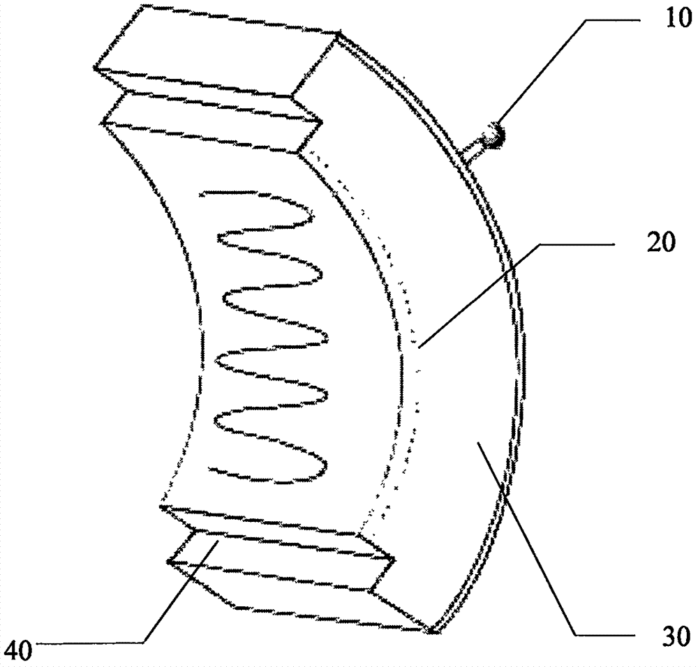
[0021] refer to figure 1 , is a schematic diagram of a thermal insulation modular structure applied to high-temperature pipeline heat transfer, 10 is a vacuum gauge, 20 is a temperature sensor, 30 is a gradient function thermal insulation core material, 40 is a stainless steel shell, the thickness of the modular structure is 12mm, and the length is 600mm , the thickness of the stainless steel film is 0.2mm, and the gradient function insulation core material is a ceramic fiber paper layer with a single-layer fiber paper thickness of 15 μm, a glass fiber paper layer with a single-layer fiber paper thickness of 10 μm, and aluminum-plastic film vacuum insulation. The thermal conductivity of the board is 0.035W / (m K) at room temperature and 0.06W / (m K) at 500°C; the temperature sensor is located on the inner surface of the insulation modular structure and is used to monitor the temperature of the outer wall of the pipeline in real time; the vacuum gauge Located in the shell of the ...

Embodiment 2

[0030] refer to figure 1 , is a schematic diagram of a thermal insulation modular structure applied to high-temperature pipeline heat transfer, 10 is a vacuum gauge, 20 is a temperature sensor, 30 is a gradient function thermal insulation core material, 40 is a stainless steel shell, the thickness of the modular structure is 45mm, and the length is 1000mm , the thickness of the stainless steel shell is 0.5mm, and the insulation core material with gradient function is a ceramic fiber paper layer with a single-layer fiber paper thickness of 5 μm, a glass fiber paper layer with a single-layer fiber paper thickness of 2 μm, and aluminum-plastic film vacuum insulation. The thermal conductivity of the plate is 0.025W / (m K) at room temperature and 0.05W / (m K) at 500°C; the temperature sensor is located on the inner surface of the insulation modular structure for real-time monitoring of the temperature of the outer wall of the pipeline; the vacuum gauge is located at The thermal insul...


PUM

PropertyMeasurementUnit
Thicknessaaaaaaaaaa
Lengthaaaaaaaaaa
Thicknessaaaaaaaaaa

Abstract

The invention discloses a heat preservation modular structure applied to high-temperature pipeline heat transfer. The structure comprises stainless steel thin films, a gradient function heat-preservation core material, a temperature sensor and a vacuum gauge, the stainless steel thin films are subjected to seamless welding, and the gradient function heat-preservation core material is composed of a ceramic fiber paper layer, a fiberglass paper layer and an aluminum-plastic film vacuum heat insulation plate. All parts synergistically take effects, and the heat preservation property is greatly improved. The temperature sensor is located on the inner surface of the heat preservation modular structure, and the vacuum gauge is located on an outer shell of the heat preservation modular structure. All the parts are integrally formed, the interior is vacuumized, optimization of the heat preservation effect is achieved, the overall heat conductivity coefficient is about 0.04 W / (m.K), and the thickness of the heat preservation layer is greatly decreased; and meanwhile through integrated structural design, construction of workers and subsequent maintaining and repairing are facilitated, the maintaining period is shortened, and economic benefits are greatly increased.

Description

technical field [0001] The patent of the present invention relates to a thermal insulation modular structure, in particular to a thermal insulation modular structure applied to heat transfer of high-temperature pipelines. technical background [0002] With the development of the nuclear power industry, people pay more and more attention to nuclear energy, an efficient and clean energy. The country also has a clear plan for the use of nuclear energy. The rational use of nuclear energy under the premise of ensuring safety can effectively alleviate the increasingly tense energy crisis. In the fast reactor, in order to isolate the radioactive core from the power generation part, the sodium cooling system is divided into a primary loop and a secondary loop. The primary loop is directly in contact with the core, and the heat is transferred to the secondary loop through a heat exchanger. The sodium flow in the secondary circuit heats the boiler to generate steam at about 483°C, whi...

Claims


Application Information

Patent Timeline
IPC IPC(8): F16L59/02F16L59/10F16L59/065G01K13/00G01L21/00
CPCF16L59/029F16L59/065F16L59/10G01K13/00G01L21/00
Inventor 陈照峰叶信立
Owner NANJING UNIV OF AERONAUTICS & ASTRONAUTICS
Learn More