


Quick Research
Generate reliable direction feasibility study reports for your R&D in just a few steps.

Technical Q&A
Discover and master advanced knowledge NOW. Basics, ideas, possibilities, all at once.

Find Solutions
As an expert in R&D theories, this can generate solutions to your technical problems instantly.

Evaluate Feasibility
Analyze your overall solution with one click, know your potential R&D risks in advance.

Monitor Landscape
Get weekly tech updates, stay abreast of the latest tech innovations and key insights.
Inverter topology circuit for suppressing leakage current in photovoltaic grid-connected system and control method thereof
A technology of topology circuit and leakage current, applied in photovoltaic power generation, AC network circuit, circuit device and other directions, to achieve the effect of suppressing leakage current, simple modulation method and good reliability
- Summary
- Abstract
- Description
- Claims
- Application Information
AI Technical Summary
Problems solved by technology
Method used
Image


Examples
specific Embodiment approach 1
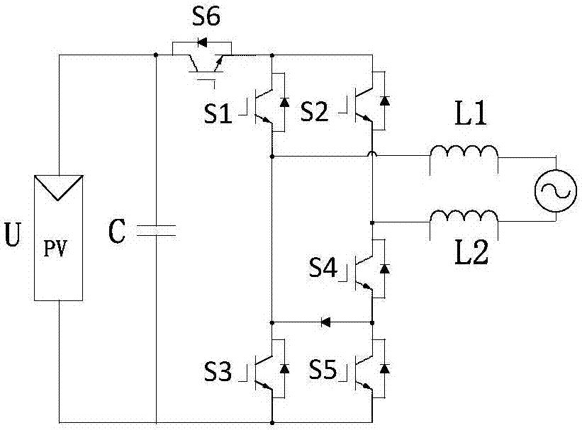
[0038] Specific implementation mode one, see figure 1 Describe this specific embodiment. The inverter topology used to suppress leakage current in the photovoltaic grid-connected system described in this specific embodiment includes a photovoltaic array PV, an incoming and outgoing constant voltage capacitor C, a diode D, and a first controlled switch tube S1 , the second controlled switch tube S2, the third controlled switch tube S3, the fourth controlled switch tube S4, the fifth controlled switch tube S5, the sixth controlled switch tube S6, the first inductance L1 and the second inductance L2 And the power grid constitutes an inverter circuit with six controlled switch tubes.
[0039] The capacitor C is connected in parallel with the power supply U,
[0040] The positive pole of the power supply U is connected to the collector of the sixth controlled switch tube S6 at the same time,
[0041] The negative pole of the power supply U is connected to the emitter of the third...
specific Embodiment approach 2
[0048] Embodiment 2. The difference between this embodiment and the topology of the inverter used to suppress the leakage current in the photovoltaic grid-connected system described in Embodiment 1 is that the controlled switching tube is an IGBT, a MOSFET or a controllable One or a combination of several silicon rectifier elements.
[0049] figure 2 Figure 1-5 shows four working states of the topology structure of the present invention, the direction of the arrow is the direction of the inverter current, and the voltage value of the power supply is U.
[0050] figure 2It shows the schematic diagram of positive half-cycle working principle of the inverter topology used to suppress leakage current in the photovoltaic grid-connected system. During the positive half-cycle power processing stage, the fourth controllable switch S4 is always on, and the second The tube S2 and the third controllable switch tube S3 are always kept off, when the first controllable switch tube S1, t...
PUM
 Abstract
Description
Claims
Application Information
 - R&D Engineer
- R&D Manager
- IP Professional
- Industry Leading Data Capabilities
- Powerful AI technology
- Patent DNA Extraction
Browse by: Latest US Patents, China's latest patents, Technical Efficacy Thesaurus, Application Domain, Technology Topic, Popular Technical Reports.
© 2024 PatSnap. All rights reserved.Legal|Privacy policy|Modern Slavery Act Transparency Statement|Sitemap|About US| Contact US: help@patsnap.com