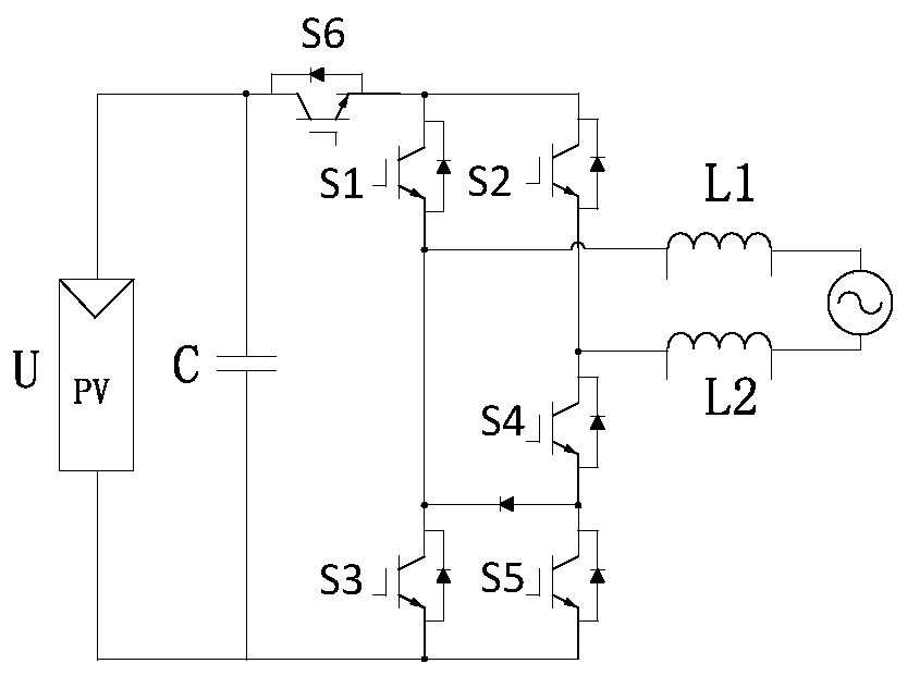
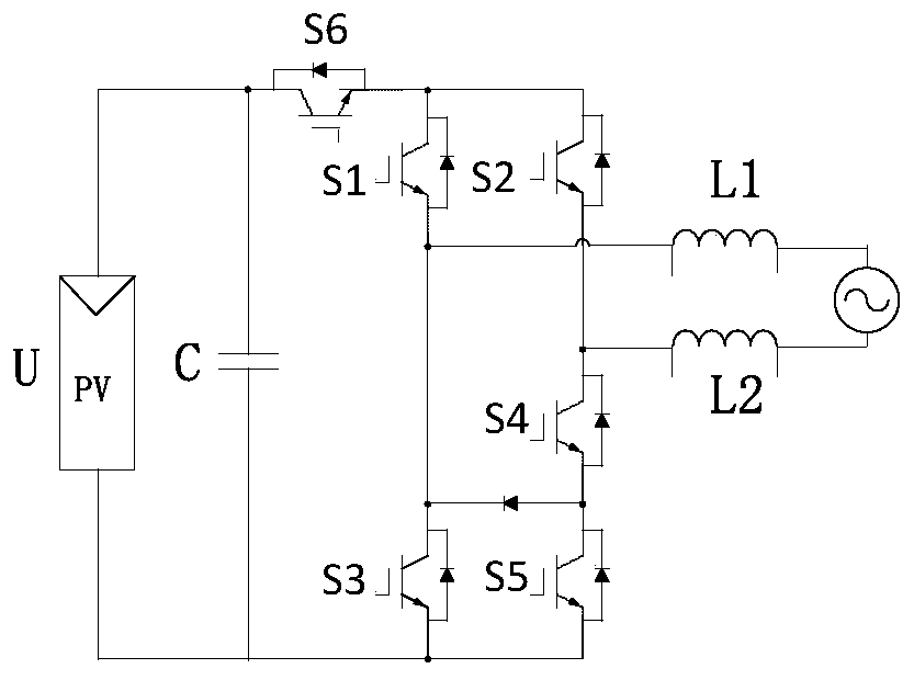
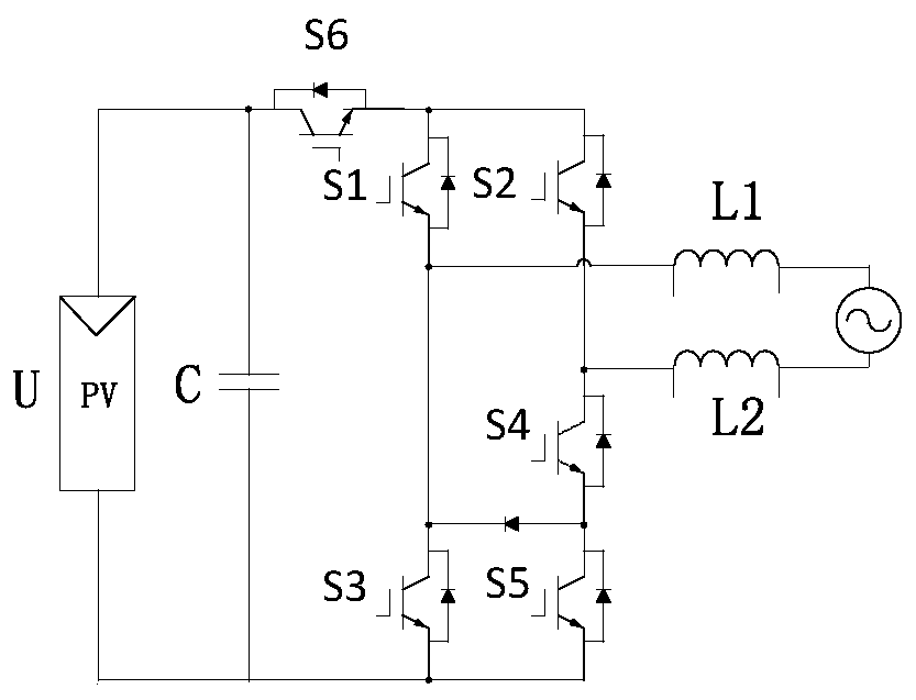
Inverter topology circuit and control method for suppressing leakage current in photovoltaic grid-connected system
A topology circuit and leakage current technology, applied in photovoltaic power generation, AC network circuits, circuit devices, etc., to achieve the effect of simple circuit topology, good thermal stress balancing effect, and output power quality.
Active Publication Date: 2019-10-01
深圳市富嘉新能源有限公司
View PDF5 Cites 0 Cited by
- Summary
- Abstract
- Description
- Claims
- Application Information
AI Technical Summary
Problems solved by technology
Compared with the isolated structure, the non-isolated structure has an advantage in efficiency, but so far, some power switches of the non-isolated grid-connected inverter still work in the hard switching state
Method used
View moreImage
Smart ImageViewing Examples
Examples
specific Embodiment approach 1
specific Embodiment approach 2
Login to View More PUM
 Abstract
The invention discloses an inverter topology circuit for suppressing leakage current in a photovoltaic grid-connected system and a control method thereof, comprising a first controlled switch tube S1, a second controlled switch tube S2, a third controlled switch tube S3, the fourth controlled switch tube S4, the fifth controlled switch tube S5, the sixth controlled switch tube S6, the diode D, the power supply U, the capacitor C, the first inductance L1 and the second inductance L2, the inverter proposed by the present invention The inverter topology can be regarded as a compromise between the H5 topology and the HERIC topology. The circuit topology is simple, the operating efficiency is high, and the reliability is good. The influence of distortion can avoid the distortion of current waveform caused by the influence of grid power fluctuation or working in non-unity power factor. Improve the safety factor of the inverter and realize the improvement of the output power quality.
Description
technical field The invention belongs to the technical field of power electronic power converters. Specifically related to the total non-isolated photovoltaic grid-connected inverter in the future. Background technique In order to ensure the safe and reliable operation of the system and realize voltage adjustment and electrical isolation, the traditional grid-connected inverter system generally installs a power frequency isolation transformer at the output end. However, power frequency isolation transformers are bulky, costly, and have large losses, which affect the overall efficiency of the system. Therefore, the transformerless non-isolated grid-connected inverter is a hot research topic at present. Although removing the power frequency transformer can improve the overall efficiency of the grid-connected inverter system, it brings some new problems, such as common-mode current and DC injection. In order to effectively suppress the leakage current, at present, experts a...
Claims
Login to View More Application Information
Patent Timeline
 Patent Type & Authority Patents(China)
IPC IPC(8): H02M7/5387H02M1/32H02J3/38
CPCH02J3/383H02M1/32H02M7/5387H02M1/0038Y02E10/56
Inventor 廖志凌张凯丁蔓菁崔清华顾赟
Owner 深圳市富嘉新能源有限公司
- R&D Engineer
- R&D Manager
- IP Professional
- Industry Leading Data Capabilities
- Powerful AI technology
- Patent DNA Extraction
Learn More Browse by: Latest US Patents, China's latest patents, Technical Efficacy Thesaurus, Application Domain, Technology Topic, Popular Technical Reports.
© 2024 PatSnap. All rights reserved.Legal|Privacy policy|Modern Slavery Act Transparency Statement|Sitemap|About US| Contact US: help@patsnap.com


