
Method for scraping crude oil channel wall wax layer

A channel wall and wax layer technology, applied in earthwork drilling, cleaning equipment, wellbore/well components, etc., can solve problems such as oil pressure rise, oil pipe blockage, oil well wax deposition, etc.

Inactive Publication Date: 2017-09-26
SICHUAN XILIN OIL SUPPLIES EQUIP
View PDF9 Cites 2 Cited by
  • Summary
  • Abstract
  • Description
  • Claims
  • Application Information

AI Technical Summary

Problems solved by technology

[0006] The purpose of the present invention is to provide a method for scraping off the wax layer on the wall of the crude oil channel, so as to solve the problems of wax deposition in the oil well due to the high wax content of the crude oil in some places, resulting in the reduction of the crude oil circulation channel, the increase of the oil pressure, and the blockage of the oil pipe.

Method used


Image

  • Method for scraping crude oil channel wall wax layer
  • Method for scraping crude oil channel wall wax layer
  • Method for scraping crude oil channel wall wax layer

Examples


Embodiment 1

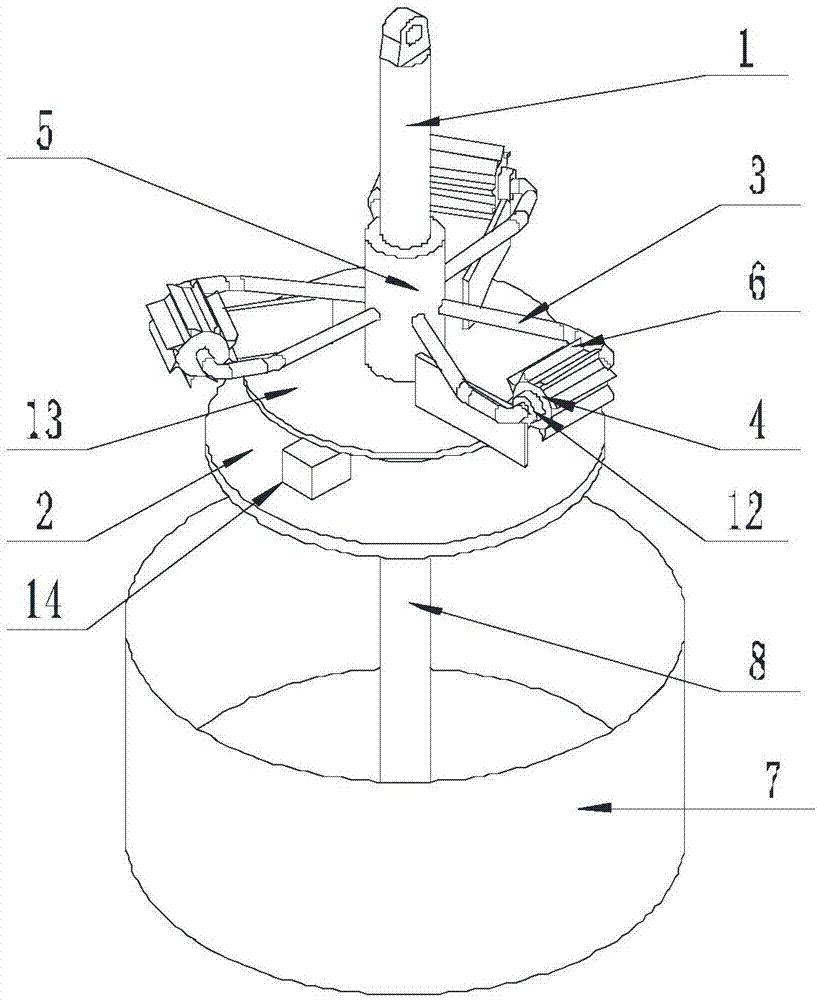
[0036] Such as Figure 1-Figure 6 Shown, the method that the present invention scrapes off crude oil passage wall wax layer, comprises the steps:

[0037] Step A preparation: fix the winch 9 next to the oil well, fix the fixed wheel 11 above the oil well inlet, connect one end of the wire rope 10 to the winch 9, and connect the other end of the wire rope 10 to one end of the connecting shaft 1 after bypassing the fixed wheel 11;

[0038] Step B wax scraping: start the winch 9, lengthen the wire rope 10, so that the wax removal assembly falls along the diameter of the oil well;

[0039] Start the driving device I and the driving device II at the same time, the driving device II makes the scraper 6 rotate around the axis of the support cylinder 4 to scrape off the wax layer on the well wall; the driving device I makes the scraper assembly rotate around the connecting shaft 1 to Scrape off the wax layer around the well wall;

[0040] Step C Exit: Start the winch 9, shorten the ...

Embodiment 2

[0045] The present invention is based on embodiment 1, and the present invention is further described.

[0046] Such as Figure 1-Figure 6As shown, in the method for scraping the wax layer on the wall of the crude oil channel in the present invention, the support shaft 3 is bent into a C shape, and its ends are connected to the side wall of the installation cylinder 5, and the support cylinder 4 is located on the support shaft 3 away from the installation cylinder 5 on the shaft.

[0047] Further, the cross-section of the scraper 6 is triangular, its base is connected to the support cylinder 4, its waistlines are all arc-shaped, and the inner concave surface of one waistline faces the center of the triangle, and the inner concave surface of the other waistline The concave face faces away from the center of the triangle. The cross-section of the scraper 6 is set as a triangle, and the two waistlines are arcs, which is beneficial for the scraper 6 to scrape off the wax layer o...

Embodiment 3

[0052] The present invention further explains the suspension device on the basis of Embodiment 2.

[0053] Such as Figure 1-Figure 6 As shown, the method for scraping the wax layer on the wall of the crude oil channel in the present invention, the suspension device includes a fixed wheel 11, a winch 9 and a steel wire rope 10, one end of the steel wire rope 10 is connected with the winch 9, and the other end of the steel rope walks around the fixed wheel After 11, it is connected with the connecting shaft 1, and the winch 9 makes the connecting shaft 1 move along the axis perpendicular to the horizontal plane by retracting and unwinding the wire rope.


PUM


Abstract

The invention discloses a method for scraping a crude oil channel wall wax layer. The method comprises a step A: a winch is fixed beside an oil well, a fixed wheel is fixed above an oil well inlet, one end of a steel wire rope is connected to the winch, and the other end of the steel wire rope bypasses the fixed wheel and then is connected with one end of a connecting shaft; a step B: the winch is started, and the steel wire rope is lengthened; and a driving device I and a driving device II are started. A wax removal assembly comprises the connecting shaft, a supporting plate, a scraper assembly, the driving device I, the driving device II and an installation barrel arranged on the connecting shaft in a sleeved mode. The scraper assembly comprises a supporting shaft and a supporting barrel. The side wall of the supporting barrel is provided with a scraper, the scraper is rotated through components such as a lifting device to remove wax on the oil well wall, and negative conditions such as reduction of a crude oil channel, oil pressure rise and oil pipe blockage are avoided, to ensure that crude oil circulates normally and the crude oil is exploited smoothly.

Description

technical field [0001] The invention relates to a method for removing wax, in particular to a method for scraping off the wax layer on the wall of a crude oil channel. Background technique [0002] Drilling is the project of using mechanical equipment to drill the formation into cylindrical holes with a certain depth. According to the way of rock crushing and the type of tools used, it can be divided into ton drill and rotary drill. [0003] Ton drill, also known as impact drill. The drill bit is sent to the bottom of the well with a wire rope, and the beam mechanism is driven by power, so that one end of the beam moves up and down, and the wire rope and the drill bit are driven to produce an up and down impact to break the rock. The drilling speed of sudden drilling is slow, the efficiency is low, and it cannot adapt to the drilling requirements of increasing well depth and complex formations, and is gradually replaced by rotary drilling. But it has the advantages of sim...

Claims


Application Information

Patent Timeline
IPC IPC(8): E21B37/02
CPCE21B37/02
Inventor 贺昶明
Owner SICHUAN XILIN OIL SUPPLIES EQUIP
Learn More