
Optical current transformer having anti-vibration function and anti-vibration interference method realized by adopting current transformer

A current transformer and current sensor technology, applied in voltage/current isolation, measurement using digital measurement technology, etc., can solve problems affecting the accuracy of output results, external vibration interference of optical current transformers, etc., to improve accuracy, The effect of reducing the impact

Inactive Publication Date: 2017-09-22
STATE GRID LIAONING ELECTRIC POWER RES INST +3
View PDF5 Cites 8 Cited by
  • Summary
  • Abstract
  • Description
  • Claims
  • Application Information

AI Technical Summary

Problems solved by technology

[0004] The purpose of the present invention is to solve the problem that the accuracy of the output results of the existing optical current transformer is affected by external vibration interference. The present invention provides an optical current transformer with anti-vibration function and an anti-vibration Methods of Vibration Disturbance

Method used


Image

  • Optical current transformer having anti-vibration function and anti-vibration interference method realized by adopting current transformer
  • Optical current transformer having anti-vibration function and anti-vibration interference method realized by adopting current transformer
  • Optical current transformer having anti-vibration function and anti-vibration interference method realized by adopting current transformer

Examples


specific Embodiment approach 1

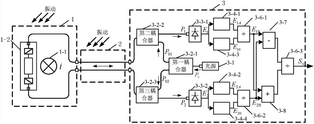
[0041] Specific implementation mode one: see figure 1 Describe this embodiment mode, an optical current transformer with anti-vibration function described in this embodiment mode, which includes a primary processing part 1, a transmission fiber part 2 and a secondary processing part 3;

[0042] Two-way analog optical information exchange is performed between the primary processing part 1 and the secondary processing part 3 through the transmission fiber part 2,

[0043] The primary processing part 1 is used to induce the current signal, and load the induced current signal on the carrier light generated by the secondary processing part 3, and the secondary processing part 3 performs anti-vibration processing on the carrier light loaded with the induced current, thereby obtaining the processed The subsequent current information.

[0044] In this embodiment, the present invention effectively eliminates or weakens the influence of vibration interference on the output results throug...

specific Embodiment approach 2

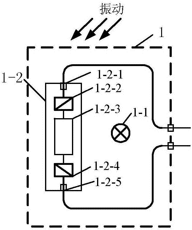
[0045] Specific implementation mode two: see figure 1 Describe this embodiment. The difference between this embodiment and the optical current transformer with anti-vibration function described in Embodiment 1 is that the primary processing part 1 includes a conductor 1-1 and a magneto-optical glass type current sensor 1 -2;

[0046] The secondary processing part 3 includes a light source 3-1, a first coupler 3-2-1, a second coupler 3-2-2, a third coupler 3-2-3, a first photodetector 3-3- 1. The second photodetector 3-3-2, the first low-pass filter 3-4-1, the second low-pass filter 3-4-2, the third low-pass filter 3-4-3, the first low-pass filter Four low-pass filters 3-4-4, first divider 3-6-1, second divider 3-6-2, third divider 3-6-3, subtractor 3-7 and adder 3 -8;

[0047] Magneto-optic glass type current sensor 1-2, used for collecting current information of conductor 1-1,

[0048] The light emitted by the light source 3-1 is split into two beams with equal success ra...

specific Embodiment approach 3

[0055] Specific implementation mode three: see figure 1 This embodiment is described. The difference between this embodiment and the optical current transformer with anti-vibration function described in the second embodiment is that the first coupler 3-2-1, the second coupler 3- Both 2-2 and the third coupler 3-2-3 are 3dB fiber couplers.


PUM


Abstract

The invention discloses an optical current transformer having an anti-vibration function and an anti-vibration interference method realized by adopting the current transformer, and belongs to the electric power system current measuring field. A problem that the accuracy of the output results of the conventional optical current transformer is affected by external vibration interferences is solved. The optical current transformer comprises a primary processing part, a transmission optical fiber part, and a secondary processing part. Bidirectional simulation optical information exchange between the primary processing part and the secondary processing part is carried out by the transmission optical fiber part. The primary processing part is used to sense current signals, and is used to load the sensed current signals on carrier light generated by the secondary processing part, and the secondary processing part is used for the anti-vibration processing of the carrier light of the loaded and sensed current, and therefore processed current information is acquired. The optical current transformer and the anti-vibration interference method are mainly used for the electric power system current measuring field having high vibration interference intensity.

Description

technical field [0001] The invention belongs to the field of electric system current measurement, and in particular relates to a method for reducing the influence of vibration interference of an optical current transformer. Background technique [0002] Optical current transformers have many advantages that traditional electromagnetic current transformers cannot match: excellent insulation performance, no transient magnetic saturation, large dynamic measurement range, wide frequency response, strong anti-electromagnetic interference ability, small size and light weight, easy to use with Digital equipment interfaces, etc., are especially suitable for the measurement of high voltage and high current, and have broad application prospects in power systems. The power system requires equipment to have high reliability and accuracy, which requires all components of the optical current transformer: the optical current sensing unit, the transmission fiber link, and the secondary phot...

Claims


Application Information

Patent Timeline
IPC IPC(8): G01R15/24G01R19/25
Inventor 吴志琪于同伟李籽良张国庆郭志忠于文斌王贵忠
Owner STATE GRID LIAONING ELECTRIC POWER RES INST
Learn More