Concealed door stopper
An invisible door and door suction technology, which is applied to lighting devices, lighting and heating equipment, building fastening devices, etc., can solve problems such as poor safety, and achieve the effects of reducing production costs, simple and novel structure, and fast and convenient installation.
- Summary
- Abstract
- Description
- Claims
- Application Information
AI Technical Summary
Problems solved by technology
Method used
Image
Examples
Embodiment 1
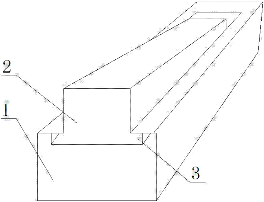
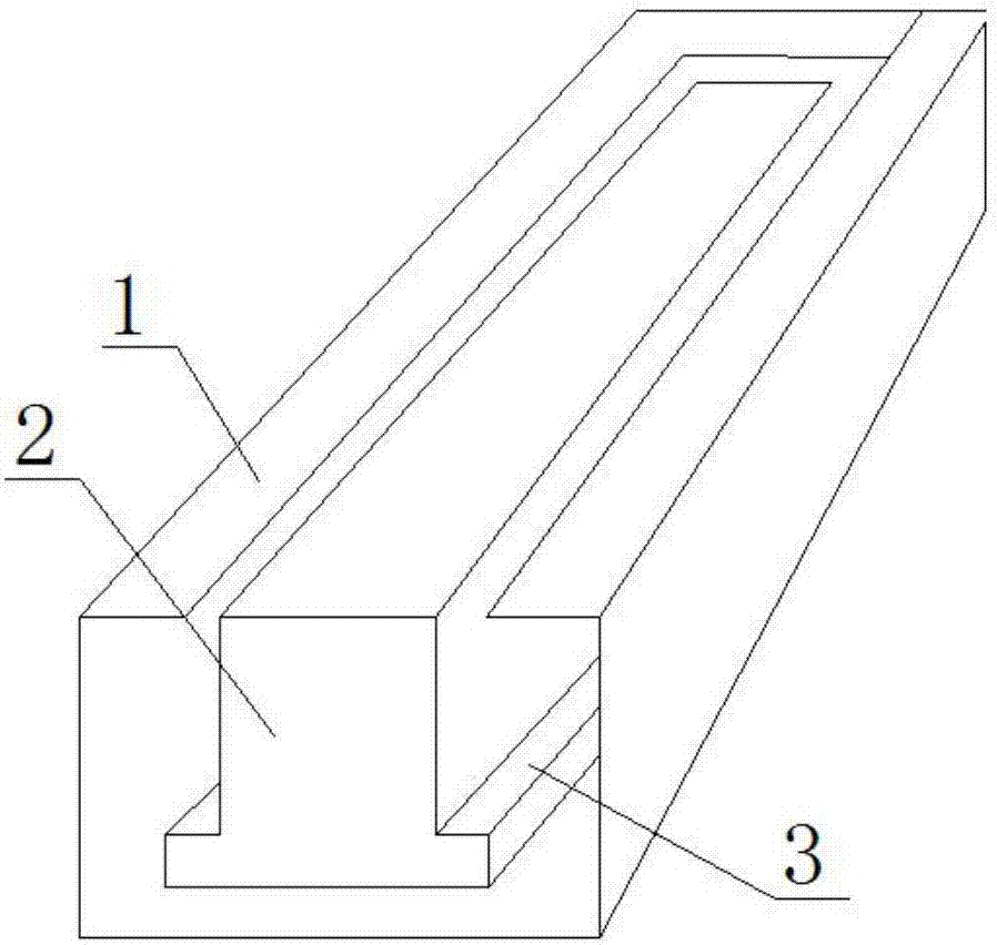
[0058] like Figure 1-5 , Figure 7 , 10 As shown in any figure, the invisible door stopper includes a door stopper main body and a braking mechanism. The door stopper main body includes a main body shell 1, a main movable rod 2, an elastic device 7, a rotating shaft 6 and a limit protrusion. The elastic device 7 is provided with It is a compression spring, and the top of the main body shell 1 is provided with a guide channel that cooperates with the main movable rod 2. One end of the main movable rod 2 is connected to the main body shell 1 through the rotating shaft 6, and the other end of the main movable rod 2 is moved through the elastic device 7. Embedded in the guide channel of the main body shell 1, the main body shell 1 is set as a hollow cuboid structure with a rectangular guide channel at the top, the main body shell 1 is set as a hollow cuboid structure, the main movable rod 2 and the guide channel that cooperates with it are respectively Set as a cylindrical stru...
Embodiment 2
[0068] On the basis of Example 1, different from Example 1, such as Image 6 , 8 , 9 As shown in any figure, the invisible door stopper includes a door stopper main body and a braking mechanism. The door stopper main body includes a main body shell 1, a main movable rod 2, an elastic device 7, a rotating shaft 6 and a limit protrusion, and the elastic device 7 is set It is a pressure spring, and the top of the main body shell 1 is provided with a guide channel that cooperates with the main movable rod 2. One end of the main movable rod 2 is connected to the main body shell 1 through the rotating shaft 6, and the main body shell 1 is set as a rectangular guide channel at the top. Hollow cuboid structure, the other end of the main movable rod 2 is movably embedded in the guide channel of the main body shell 1 through the elastic device 7, and the main movable rod 2 and the guide channel cooperating with it are respectively set as a cylindrical structure with a square cross secti...
Embodiment 3
[0078] On the basis of Example 1, different from Example 1, such as Figure 15 , 16 As shown, the brake mechanism includes a pressing block 11, a limit block 17, a spring a16, a spring b12, a horizontal connecting rod 14, a vertical connecting rod 20 and a disc 19, and the disc 19 is embedded in the main body along the radial direction In the side wall of the shell 1, a central shaft 18 is provided at the center of the turntable, a groove a15 is provided on the inner side wall of the main body shell 1, a limit block 17 is embedded in the groove a15, and a groove b13, the pressing block 11 is arranged in the groove b13, one end of the horizontal connecting rod 14 and the vertical connecting rod 20 are arranged on the disc 19 along the horizontal direction and the vertical direction respectively, and the other end of the horizontal connecting rod 14 and the limiting The position block 17 is connected, the other end of the vertical limit rod is connected to the pressing block 11...
PUM
 Abstract
Description
Claims
Application Information
 - R&D Engineer
- R&D Manager
- IP Professional
- Industry Leading Data Capabilities
- Powerful AI technology
- Patent DNA Extraction
Browse by: Latest US Patents, China's latest patents, Technical Efficacy Thesaurus, Application Domain, Technology Topic, Popular Technical Reports.
© 2024 PatSnap. All rights reserved.Legal|Privacy policy|Modern Slavery Act Transparency Statement|Sitemap|About US| Contact US: help@patsnap.com


