
Mine tailing dry discharge system and method

A technology of dry discharge and tailings, which is applied in separation methods, chemical instruments and methods, dehydration/drying/thickened sludge treatment, etc. It can solve the problems of high production cost, high price, and inability to dry discharge, etc., and achieve low production cost , Low production power consumption and low maintenance costs

Pending Publication Date: 2017-09-22
烟台禹顺环保科技有限公司
View PDF8 Cites 6 Cited by
  • Summary
  • Abstract
  • Description
  • Claims
  • Application Information

AI Technical Summary

Problems solved by technology

This solution discharges discontinuously, especially for tailings with severe material mudification or high content of primary mud, the material in the filter press is likely to form a "slurry" phenomenon, and thus cannot be discharged dryly, and buffer equipment may be required for some processes
Take the tailings dry discharge plant with a processing capacity of 4000T / D as an example: the main equipment includes a thickener (45-53 meters in diameter), a box filter of 1060m 2 8 sets, 16 wear-resistant sand pumps and other auxiliary equipment, high power consumption, the total power is 350kw, the life of the filter cloth is only 2-3 months, the total investment reaches 7.5 million, the production cost is high, about 5-8 per ton Yuan, the material moisture after dry discharge is 16%-20%, and it covers a large area, low moisture, but expensive, but it is often used for concentrate dehydration

Method used


Image

  • Mine tailing dry discharge system and method
  • Mine tailing dry discharge system and method
  • Mine tailing dry discharge system and method

Examples


Embodiment Construction

[0050] The principles and features of the present invention are described below in conjunction with the accompanying drawings, and the examples given are only used to explain the present invention, and are not intended to limit the scope of the present invention.

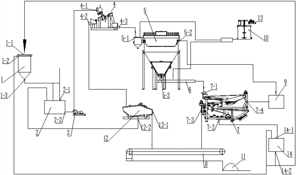
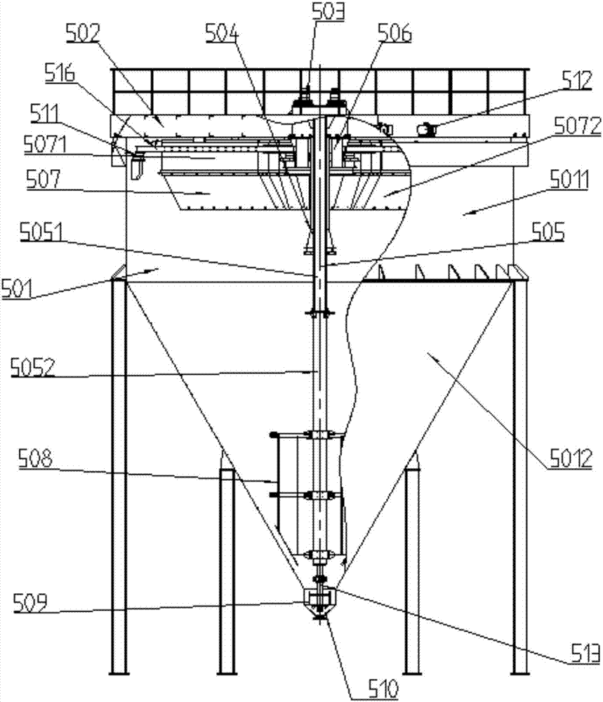
[0051] Such as figure 1 As shown, a tailings dry discharge system includes a slurry supply device, a thickening cyclone 4, a thickener 5, an unpowered thickener 1, a dewatering screen 12, a fine grain dehydrator 7 and a belt conveyor 8,

[0052] The outlet of the pulp supply device is connected to the inlet 4-1 of the concentrated cyclone, the outlet of the concentrated cyclone includes a concentrated material outlet 4-2 and a thin liquid outlet 4-3, and the concentrated material outlet 4-2 is connected to the The inlet of the dewatering screen is connected, the thin liquid outlet 4-3 is connected with the inlet 5-1 of the thickener, the dewatering screen 12 includes a dry outlet 12-1 and a filtrate outlet 12-2, and...


PUM


Abstract

The invention relates to a mine tailing dry discharge system, which includes a mine supplying apparatus, a concentration cyclone, a thickening machine, a non-power thickener, a high-frequency dewatering screen, a fine granule dewaterer and a belt conveyer. The mine supplying apparatus is connected to the concentration cyclone; an outlet of the concentration cyclone includes a concentrate outlet and a dilute liquid outlet, wherein the concentrate outlet is connected to an inlet of the dewatering screen, and the dilute liquid outlet is connected to an inlet of the thickening machine; an outlet of the dewatering screen includes a dry discharge outlet and a filtrate outlet, wherein the belt conveyer is arranged below the dry discharge outlet, and the filtrate outlet is connected to an inlet of the mine supplying apparatus; an outlet of the thickening machine comprises an upper outlet and a lower outlet, wherein the lower outlet is connected to an inlet of the fine granule dewaterer, and the upper outlet is connected to a water recycling tank of the thickening machine; and the outlet of the fine granule dewaterer includes a filter cake outlet and a press filtration flushing mixed water outlet, wherein the belt conveyer is located below the filter cake outlet and the press filtration flushing mixed water outlet is connected to a water recycling tank of the dewaterer.

Description

technical field [0001] The invention relates to a tailings dry discharge system and method. Background technique [0002] Due to the tailings wet discharge method used in the original mines, it occupies a large amount of land, seriously affects the ecological environment, is prone to safety hazards, and greatly wastes water resources. Now the country has made tailings dry discharge a policy requirement, and some areas have put tailings Mine trunk row is a prerequisite for the establishment of a mine development project and the resumption of production in the original mine; [0003] Tailings dry discharge is the process of solid-liquid separation, that is, the tailings slurry output through the beneficiation process is processed by equipment to form slag with low water content, easy to settle and solidify, and use the site for storage. The slag can be transferred to a fixed location for dry stacking Since the concentrate dehydration process and technology are now very mature...

Claims


Application Information

Patent Timeline
IPC IPC(8): C02F11/12C02F11/14B01D21/02B01D21/28B01D21/01B01D33/04B01D33/056B01D36/04
CPCB01D21/01B01D21/02B01D21/286B01D33/04B01D33/056B01D36/04B01D36/045C02F11/121C02F11/123C02F11/127C02F11/14C02F2303/06
Inventor 袁国辉李锁陈波
Owner 烟台禹顺环保科技有限公司
Learn More