
Microwave attenuation type high stationary-phase high precision GNSS measurement type antenna and device

A microwave attenuation and high-precision technology, applied in the field of communication, can solve the problems of complex antenna structure, and achieve the effect of simple structure, uniform phase and phase-frequency characteristics, and small antenna size

Active Publication Date: 2017-09-19
叶云裳 +1
View PDF29 Cites 17 Cited by
  • Summary
  • Abstract
  • Description
  • Claims
  • Application Information

AI Technical Summary

Problems solved by technology

However, the structure of the antenna is relatively complex, and the phase-centered space normalization needs to be further improved.
[0009] However, from the application point of view, in addition to the requirements of small size, light weight, and low cost, the deviation (difference) of the antenna phase center (PCO), the variation of the antenna phase center (PCV) and the change of the group delay have become the future higher precision. The influencing factors of GNSS measurement, how to find a high-performance antenna with better phase and phase-frequency characteristics, simpler, lighter, smaller, and lower cost has become an urgent problem to be solved

Method used


Image

  • Microwave attenuation type high stationary-phase high precision GNSS measurement type antenna and device
  • Microwave attenuation type high stationary-phase high precision GNSS measurement type antenna and device
  • Microwave attenuation type high stationary-phase high precision GNSS measurement type antenna and device

Examples


Embodiment Construction

[0030] In order to make the purpose, technical solutions and advantages of the embodiments of the present invention clearer, the technical solutions in the embodiments of the present invention will be clearly and completely described below in conjunction with the drawings in the embodiments of the present invention. Obviously, the described embodiments It is a part of embodiments of the present invention, but not all embodiments. Based on the embodiments of the present invention, all other embodiments obtained by persons of ordinary skill in the art without making creative efforts belong to the protection scope of the present invention.

[0031] The embodiment of the present invention does not increase the configuration of the receiver, does not use a multi-antenna unit processing system and an adaptive antenna, and does not use a 2D / 3D choke ring structure (because this design will cause an obvious increase in antenna volume, weight and cost, If it is not suitable for miniatu...


PUM


Abstract

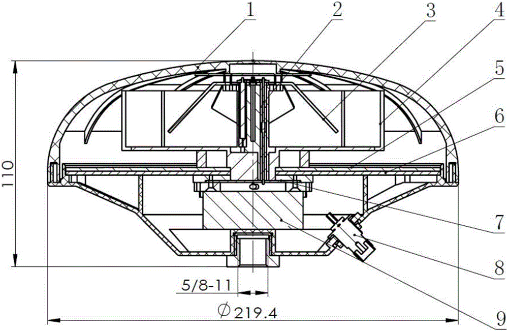
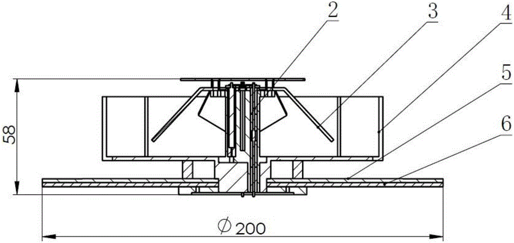
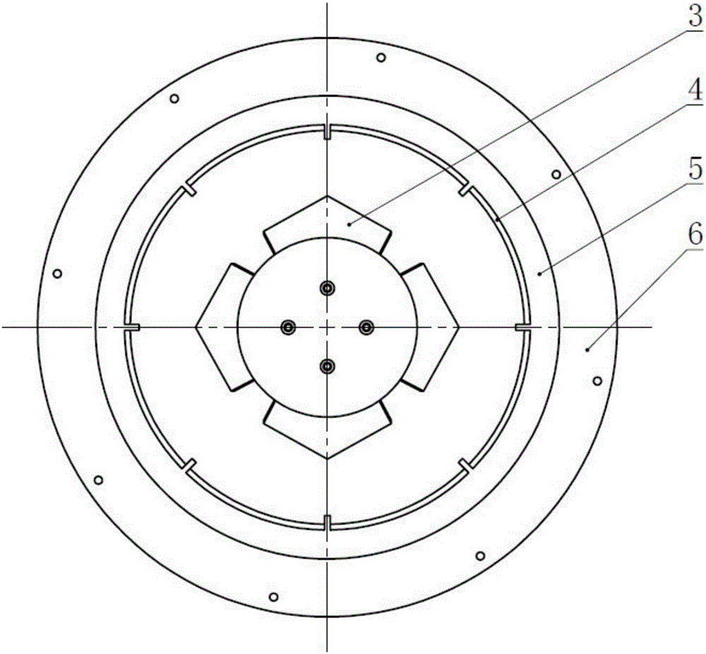
The invention discloses a microwave attenuation type high stationary-phase high precision GNSS measurement type antenna and device. The antenna comprises a sector crossed oscillator, a half-opened circular cavity, a diameter suspension plate, a microwave attenuation plate, a leading plate and a polarization separation power dividing module. The sector crossed oscillator is installed in the center of the bottom of the half-opened circular cavity through a support assembly comprising four support column bodies. The sector crossed oscillator comprises four unit oscillators. The unit oscillators are installed on the tops of the support column bodies respectively and at the same height above the cavity bottom. The setting height of the sector crossed oscillator and the depth of the half-opened circular cavity are determined through adjustment, thereby achieving flat-opening radial-plane radiation. The top of the sector crossed oscillator and the leading plate are coaxially installed in an insulation manner through a medium circular ring. The diameter suspension plate is installed at the lower bottom of the half-opened circular cavity coaxially at a certain interval. The microwave attenuation plate is close to the bottom face of the diameter suspension plate and installed coaxially. The polarization separation power dividing module and an LNA module are arranged at the bottom of the microwave attenuation plate. The antenna is small, light, simple and low in cost.

Description

technical field [0001] The invention relates to the technical field of communications, in particular to a microwave attenuation type high-phase stability and high-precision GNSS measurement antenna and equipment for a global navigation satellite system terminal receiver. Background technique [0002] Global Navigation Satellite System (GNSS) is a satellite-based radio navigation and positioning system, with omnipotence (sea, land, air, sky), global, all-weather, continuous and real-time navigation and positioning and timing functions; and can provide real-time dynamic and precise three-dimensional space coordinates, speed and time for each user. GNSS, also known as space-based PNT (position, navigation, timing) or PNOT (position, navigation, orientation, timing) system, has become a major national space and information infrastructure, and has also become an important part of reflecting the status of a modern power and the country's comprehensive national strength. sign. It...

Claims


Application Information

Patent Timeline
IPC IPC(8): H01Q1/38H01Q1/50H01Q3/26
CPCH01Q1/38H01Q1/50H01Q3/26
Inventor 叶云裳姜新发
Owner 叶云裳
Learn More