
Display apparatus

A technology for display devices and row pixels, applied to static indicators, cathode ray tube indicators, instruments, etc., can solve the problems of reducing or affecting the transmittance of display devices, maintain the transmittance, and improve the whitening of the side viewing angle problems, improving the effects of rhombus pattern problems and broken color problems

Active Publication Date: 2017-09-19
AU OPTRONICS CORP
View PDF9 Cites 18 Cited by
  • Summary
  • Abstract
  • Description
  • Claims
  • Application Information

AI Technical Summary

Problems solved by technology

If the above-mentioned sub-pixel partitioning technology is used in a high-resolution display device, it will affect the display device and reduce its transmittance

Method used


Image

  • Display apparatus
  • Display apparatus
  • Display apparatus

Examples


Embodiment Construction

[0049] The detailed features and advantages of the present invention are described in detail below in the embodiments, which are sufficient to enable those skilled in the art to understand the technical content of the present invention and implement it accordingly, and according to the contents disclosed in this specification, claims and accompanying drawings, The related objects and advantages of the present invention can be easily understood by those skilled in the art. The following examples further describe the viewpoints of the present invention in detail, but do not limit the scope of the present invention in any viewpoint. The present invention will be further described below in conjunction with the accompanying drawings.

[0050] Terms used throughout the specification and claims, unless otherwise noted, generally have each term's ordinary meaning as used in the art, in this disclosure, and in this particular context.

[0051] figure 1 It is a schematic diagram of pix...


PUM


Abstract

Provided is a display apparatus including a plurality of gate lines for outputting corresponding scanning signals to corresponding pixels, a plurality of data lines including 12 continuous data lines from left to right and used for receiving display data and outputting corresponding pixel voltages to the corresponding pixels, a gate driver electrically coupled to the gate liens and used for driving the pixels, and a data driver electrically coupled to the data lines and sued for providing data signals for the pixels, the polarities of the data provided for the 12 data lines by the data driver are respectively positive, negative, positive, negative, positive, negative, negative, positive, negative, positive, negative, and positive, each row of pixels include two types of pixels, and when the display data is the same grayscale, the data driver respectively provides two different pixel voltages to the two types of pixels.

Description

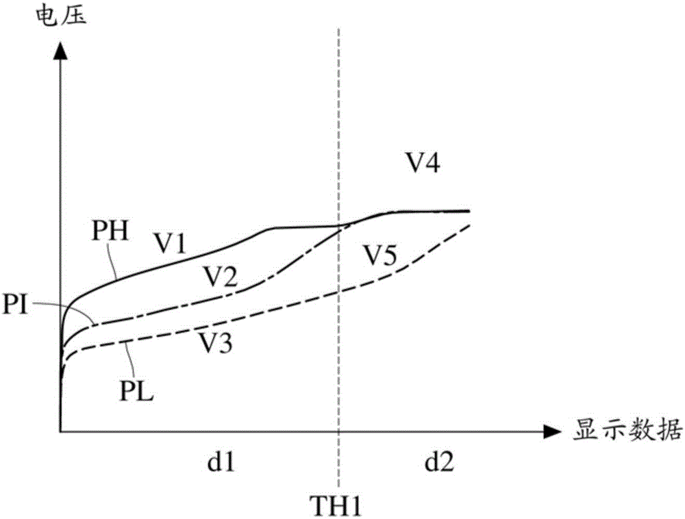
technical field [0001] The invention relates to a display device, in particular to a display device for improving color shift. Background technique [0002] In order to solve the problem of color washout at the side viewing angle of the display device, a single sub-pixel is generally divided into two areas, called the main sub-pixel area and the sub-sub-pixel area, and an appropriate circuit driving structure is used to make the sub-pixels The pixel voltages of the two regions are different, so a single sub-pixel can display two kinds of brightness, so as to improve the problem of partial whitening of the side viewing angle. [0003] In order to meet consumers' requirements for picture fineness, display devices are developing toward high resolution. If the above-mentioned sub-pixel partitioning technology is used in a high-resolution display device, it will affect the display device and reduce the transmittance. For example, when MxN pixel units receive display data with a...

Claims


Application Information

Patent Timeline
Patent Type & Authority Applications(China)
IPC IPC(8): G09G3/20
CPCG09G3/20G09G2310/027G09G3/2074G09G3/3614G09G3/3666G09G5/026G09G2300/0452G09G2320/0238G09G2320/0242G09G2320/0666G09G2320/0673G09G2320/068G09G5/02G09G2320/0219G09G2320/0276
Inventor 田堃正廖乾煌吴佳龙
Owner AU OPTRONICS CORP
Learn More