
Battery test apparatus and battery test method

A battery test and battery technology, applied in the direction of secondary battery test, measuring device, impact test, etc., can solve the problems of increasing the cost of the device, waiting for a long time, increasing the installation space, etc., to achieve rapid and safe processing, suppressing the device Effect of increased cost and installation space

Active Publication Date: 2017-09-19
ESPEC CORP
View PDF7 Cites 3 Cited by
  • Summary
  • Abstract
  • Description
  • Claims
  • Application Information

AI Technical Summary

Problems solved by technology

[0004] Because the test device disclosed in said patent document adopts the structure in which the battery is pushed out by the push unit to make the battery automatically drop into the container containing the treatment liquid, there is the following problem: Increased device cost and increased installation space
In addition, in the case of manually putting the tested battery into the treatment solution without installing a push unit in order to reduce the cost of the device, the battery is physically damaged during the test and is in an electrically unstable state, so there is a problem of hazards at work
In addition, when a battery that is on fire is put into the treatment solution, it takes a long time until the battery is completely burnt out, and it is also difficult to judge whether the battery is completely burned out.

Method used


Image

  • Battery test apparatus and battery test method
  • Battery test apparatus and battery test method
  • Battery test apparatus and battery test method

Examples


Embodiment approach 1

[0026] [Battery Test Device]

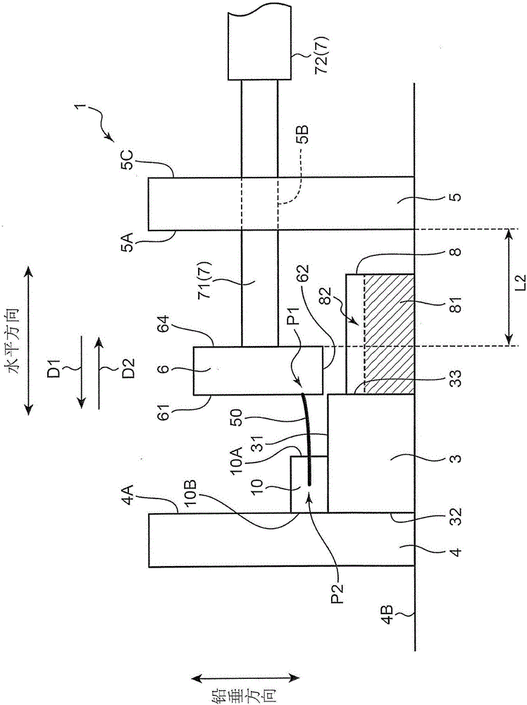
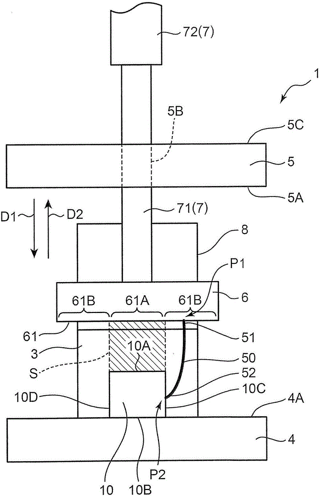
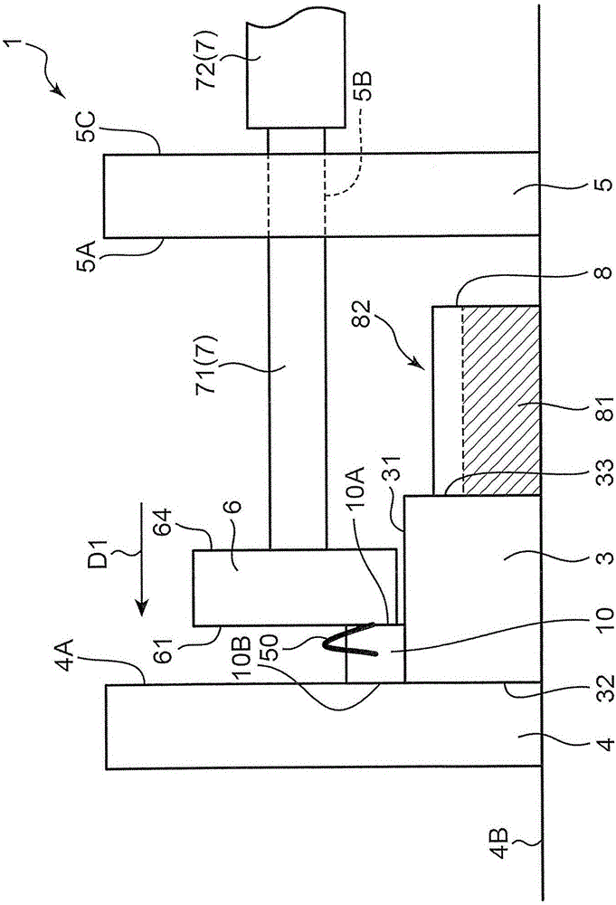
[0027] First, refer to figure 1 The configuration of the battery test device 1 according to Embodiment 1 of the present invention will be described. figure 1 The overall configuration of the battery testing device 1 is schematically shown. figure 1 The horizontal direction is the horizontal direction, and the vertical direction is the gravity direction (vertical direction).

[0028] The battery testing device 1 is a device for performing a crush test of a battery 10 that is a secondary battery for vehicles, such as a lithium ion battery. The squeeze test is one of the safety performance tests of the battery 10. Specifically, in the squeeze test, an internal short circuit is suspected to have occurred by applying a specified pressure to the battery 10, and the voltage and temperature changes at this time are detected, or by The safety performance of the battery 10 is confirmed by external observation to confirm whether the battery 10 catches fi...

Embodiment approach 2

[0063] Below, refer to Figure 7 A battery testing device 1A according to Embodiment 2 of the present invention and a battery testing method using the battery testing device 1A will be described. Embodiment 2 is basically the same as Embodiment 1, but differs from Embodiment 1 in that battery moving unit 50 is constituted by clip member 53 and coupling member 54 . Hereinafter, only the configuration of the battery transfer unit 50 that is different from the first embodiment will be described in detail.

[0064] Such as Figure 7 As shown, the battery moving unit 50 includes: a clamp member 53 having an L-shape in side view; and a connecting member 54 connecting the clamp member 53 and the pressurizing part 6 (pressurizing surface 61 ) to each other. In Embodiment 2, one end of the connecting member 54 is connected to the pressurizing surface 61 , and the other end is not directly connected to the battery 10 .

[0065] The clamp member 53 rests on the setting surface 31 Fi...

Embodiment approach 3

[0075] Below, refer to Figure 9 A battery test device according to Embodiment 3 of the present invention will be described. Embodiment 3 is basically the same as Embodiments 1 and 2, but is different from Embodiments 1 and 2 in that the nail penetration test is performed.

[0076] Figure 9 The pressurizing part 6 and its vicinity in the battery testing device are shown enlarged. Such as Figure 9 As shown, a nail portion 63 for piercing through the battery 10 is provided on the pressing surface 61 of the pressing portion 6 . Therefore, the nail portion 63 can be pierced through the battery 10 by moving the pressurizing portion 6 in a direction approaching the battery 10 based on the driving of the driving portion 7 . Accordingly, it is possible to perform a nail penetration test in which an internal short circuit occurs in the battery 10 and changes in temperature and voltage at that time, the appearance of the battery 10 , and the like can be confirmed.

[0077] Then, ...


PUM


Abstract

A battery test apparatus (1) is used for performing extrusion test or spike test on a battery (10). The battery test apparatus (1) includes: a pressurization portion (6) which is arranged in a manner that the battery (10) is positioned between the pressurization portion (6) and an opposite portion (4); a drive portion (7) for allowing the pressurization portion (6) to move in the direction (D1) for pressing the battery (10) or the direction (D2) for releasing pressurization; a container (8) for storing a processing solution (81) for allowing short circuit of the battery (10) or extinguishment of the battery (10); a battery moving unit (50) which can allow the battery (10) to move toward the container (8) on the basis that the pressurization portion (6) is driven by the drive portion (7) to move in the direction (D2) for releasing pressurization. Accordingly, increase in device cost and set space can be suppressed, the battery test apparatus can rapidly perform safe processing on the tested battery in comparison with the situation that the tested battery is put in the processing solution manually.

Description

technical field [0001] The invention relates to a battery testing device and a battery testing method. Background technique [0002] Conventionally, as tests for evaluating the safety performance of secondary batteries such as lithium ion batteries, for example, mechanical safety performance tests such as crush tests and nail penetration tests have been performed. Batteries that have undergone these tests are placed in a treatment solution such as salt water and completely electrically short-circuited for safe disposal. In addition, even if abnormal heat generation, fire, or rupture of the battery occurs during the test, the battery is placed in salt water after the fire is extinguished with a fire extinguisher. [0003] In Japanese Patent Laid-Open Publication No. 2013-224832 (hereinafter referred to as patent document), a vibration test device is disclosed as an example of a battery test device, which includes: a vibration excitation table provided with a battery as an ev...

Claims


Application Information

Patent Timeline
Patent Type & Authority Applications(China)
IPC IPC(8): G01R31/36G01R31/02G01M7/08G01M5/00
CPCG01M5/0075G01M7/08G01R31/385G01R31/50Y02E60/10H01M10/4285
Inventor 上田祐亮梶原隆志
Owner ESPEC CORP
Learn More