Light guide device and film uniformity testing apparatus and method

A technology of a light guide device and a test device, which is applied in the field of testing, can solve problems such as complex mathematical models, being affected by the environment, and high cost, and achieves the effects of simple and fast operation process, saving test time, and saving equipment investment

Inactive Publication Date: 2017-09-19
INST OF HIGH ENERGY PHYSICS CHINESE ACADEMY OF SCI
View PDF4 Cites 6 Cited by
  • Summary
  • Abstract
  • Description
  • Claims
  • Application Information

AI Technical Summary

Problems solved by technology

[0006] At present, the commonly used optical measurement methods are as follows: the ellipsometry has high sensitivity, but due to the influence of the interface layer and other factors, the mathematical model and test equipment are relatively complicated; the Michelson interferometer method, the artificial counting ring is easy to cause relatively Large errors; fiber optic spectrometers have high precision, but the tungsten halogen light is weak and easily affected by the environment, and the measurement results are unreliable; the envelope method requires a thicker film thickness to generate interference oscillations, and requires the film to absorb less light. Because semiconductor thin films are generally thin and usually have a large absorption in the visible region, it is not suitable for semiconductor thin films
The above methods are currently relatively mature in technology and high in accuracy, but there are still some disadvantages: the actual measurement process is complicated; the measurement device is complicated; the cost is expensive; for special application thin film thickness gauges, special customization is required; the input light wavelength is fixed , Different films have different peak wavelengths of light absorption and reflection, and there is an optimal value; the power of the input light is fixed, and when measuring a multilayer film, strong light incidence causes serious interference of reflected light; it is not suitable for large-area coating thickness uniformity Test; the coating thickness of closed vacuum equipment cannot be measured; the thin film of complex shape cannot be measured
For these products, the film thickness cannot be tested by transmission method

Method used


Image

  • Light guide device and film uniformity testing apparatus and method
  • Light guide device and film uniformity testing apparatus and method
  • Light guide device and film uniformity testing apparatus and method

Examples


Embodiment Construction

[0044] Example embodiments will now be described more fully with reference to the accompanying drawings. Example embodiments may, however, be embodied in many forms and should not be construed as limited to the embodiments set forth herein; rather, these embodiments are provided so that this disclosure will be thorough and complete, and will fully convey the concept of example embodiments to those skilled in the art. The same reference numerals in the drawings denote the same or similar structures, and thus their detailed descriptions will be omitted.

[0045] In the following description, numerous specific details are given in order to provide a more thorough understanding of the present invention. It will be apparent, however, to one skilled in the art that the present invention may be practiced without one or more of these details. In other examples, some technical features known in the art are not described in order to avoid confusion with the present invention.

[0046...


PUM


Abstract

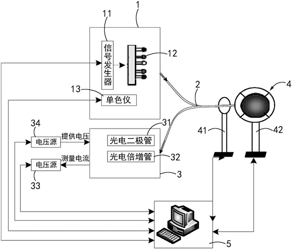
The invention discloses a light guide device and a film uniformity testing apparatus and method. The light guide device that is used for outputting light to a to-be-tested device and recovering reflected light comprises at least one incident light guide element and a plurality of reflective light guide elements. The two ends of the incident light guide element are an incident end and a transmitting end; the incident light guide element is connected with a light source device optically; and light is inputted into the incident light guide element through the incident end. A reflection end and an output end are formed at the two ends of each of the plurality of reflective light guide elements; the plurality of reflection ends are parallel to and are aligned at the transmitting end and encircle the periphery of the transmitting end; and the output ends are in light connection with optical testing device. The transmitting end of the incident light guide element and the reflection ends of the reflective light guide elements form a testing end of the light guide device; and the testing end is perpendicular to and is aligned at the surface of the to-be-tested device. In addition, a film uniformity testing apparatus is capable of testing the intensity of light outputted by the output ends so as to represent the uniformity of the film for reflection indirectly.

Description

technical field [0001] The present invention generally relates to a testing technology, and in particular, relates to a light guide device, a film uniformity testing device and a method. Background technique [0002] At present, many electronic devices, optoelectronic devices or some industrial products, in order to improve product performance or increase aesthetics, are usually coated with thin films on the surface of the products to play the functions of anti-reflection and protection. [0003] Thickness, as a basic performance parameter of the film, has a great impact on product quality and needs to be calibrated. For large-area film materials, the uneven thickness may affect the tensile strength and barrier properties of the film everywhere. affect the overall performance of the product. [0004] Ordinary film thickness gauges, for film thickness measurement methods, commonly used methods include probe method, optical method, etc. The probe method is to use a mechanica...

Claims


Application Information

Patent Timeline
IPC IPC(8): G01B11/06G01N21/17G01N21/01
CPCG01B11/0625G01N21/01G01N21/17G01N2201/068
Inventor 钱森夏经铠朱纳
Owner INST OF HIGH ENERGY PHYSICS CHINESE ACADEMY OF SCI
Why Eureka
Try Eureka