Circle drawing detection device based on wireless real-time video transmission

A real-time video and circle detection technology, which is applied in wireless communication technology and electronic fields, can solve problems such as monitor size limitation, image space limitation, and easy entanglement of cables, etc., to solve cable entanglement, solve volume limitations, and facilitate portability Effect

Active Publication Date: 2017-09-15
INST OF OPTICS & ELECTRONICS - CHINESE ACAD OF SCI
View PDF7 Cites 0 Cited by
  • Summary
  • Abstract
  • Description
  • Claims
  • Application Information

AI Technical Summary

Problems solved by technology

[0004] The invention designs and implements a circle detection device based on wireless real-time video transmission in the photoelectric capture, tracking and aiming equipment, which greatly improves the long and heavy cables behind the circle detection device in the current photoelectric capture, tracking and aiming equipment. , the stability problem caused by the fixed structure of the circle detection device; at the same time, it solves the equipment safety risk caused by the easy winding of the cable during the rotation of the turntable; realizes the video signal output by the equipment to the circle detection device Real-time transmission, and power detection of the battery-powered system; by increasing the mobile receiving end to display the transmitted video image in real time, it effectively solves the current constraints of the power supply and image cable and the volume limit of the monitor, and optically adjusts the operation of personnel The image space of the observation monitor is limited and the operability is low, which improves the convenience of optical installation and adjustment.

Method used


Image

  • Circle drawing detection device based on wireless real-time video transmission
  • Circle drawing detection device based on wireless real-time video transmission
  • Circle drawing detection device based on wireless real-time video transmission

Examples


Embodiment Construction

[0023] The specific implementation manners of the present invention will be described in detail below in conjunction with the accompanying drawings.

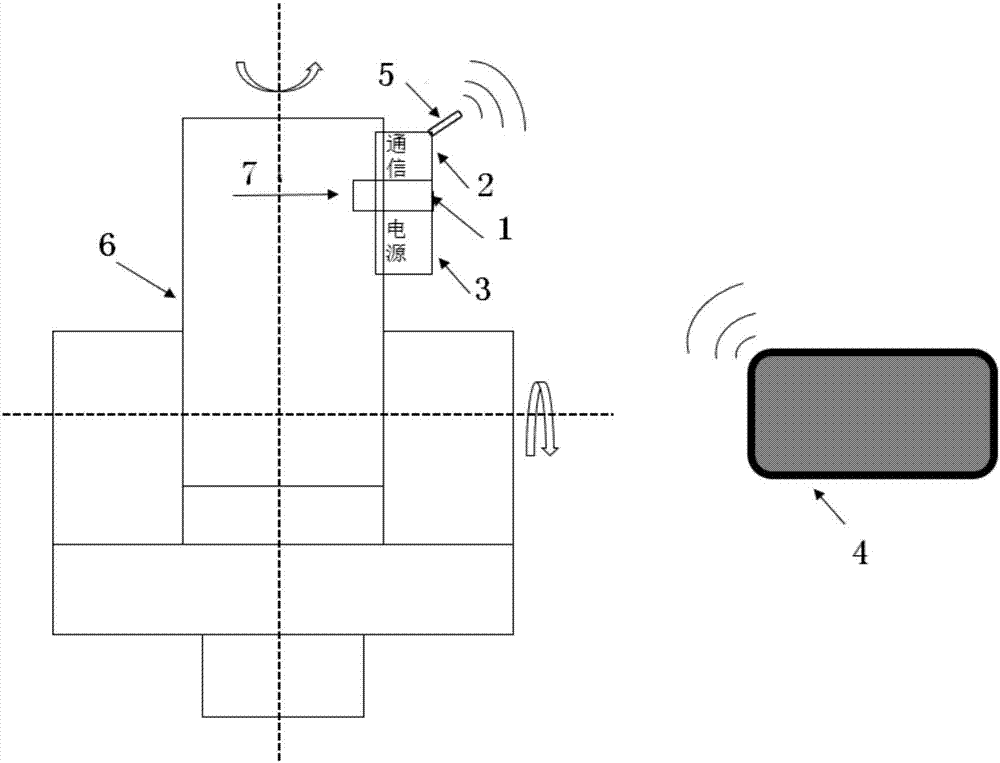
[0024] Depend on figure 1As shown, a circle detection device based on wireless real-time video transmission in the photoelectric capture tracking and aiming device 6 includes a circle detection device 1, an analog video signal to wireless module 2, a battery power supply management system 3, and a mobile receiving terminal 4, The mobile receiving terminal 4 includes a developed mobile receiving terminal APP. The laser signal 7 is the emission beam inside the telescope. In order to detect whether the emission beam inside the telescope is coaxial with the mechanical shaft of the telescope, the laser signal 7 is projected onto the circle detection device 1; wherein the circle detection device 1 is composed of an optical imaging system Composed of a CCD image sensor, etc., the circle detection device 1 can image the beam emitted by...


PUM


Abstract

The invention discloses a circle drawing detection device based on wireless real-time video transmission for overcoming the problem that the communication mode of video information output by the existing circle drawing detection device fixed on a main lens cone of photoelectric capturing, tracking and aiming equipment to an image monitor and the power supply mode of the whole circle drawing detection device are realized by wired connection, the cable is very long and very heavy, which generates very large influence to the fixation stability of the structure of the circle drawing detection device. In the invention, the video information output by the circle drawing detection device is converted into a wireless signal for transmission, the system power supply adopts battery power supply, and thus the problem of stability of the structure of the circle drawing detection device in the current equipment can be greatly improved. In addition, the circle drawing detection device disclosed by the invention can solve the safety problem of cable twisting in a turntable running process, supports mobile equipment, removes the limitation to the working space, greatly improves the convenience of the optical debugging work, and is more suitable for engineering application.

Description

technical field [0001] The invention relates to the fields of wireless communication technology and electronic technology, in particular to a circle detection device based on wireless real-time video signal transmission. Background technique [0002] In space optical communication, the coaxial relationship between the laser beam and the mechanical rotation axis is the premise and guarantee for the photoelectric capture, tracking and aiming equipment to perform laser communication as a communication terminal. Photoelectric capture, tracking and aiming equipment usually uses a Cassegrain telescope as the common antenna for optical transmission and reception. During the rotation of the telescope, if the emitted light beam inside the telescope is out of axis with the mechanical rotation axis of the telescope, the emitted light beam will be cut off or even not emitted at all. At the same time, if it is a common optical path detection, the detection will also be affected. In orde...

Claims


Application Information

Patent Timeline
IPC IPC(8): H04N7/18G01B11/27
CPCG01B11/272H04N7/18
Inventor 柳万胜陈德毅王继红贺东王亚辉鲜朝斌严棚亓波彭起王强
Owner INST OF OPTICS & ELECTRONICS - CHINESE ACAD OF SCI
Why Eureka
Try Eureka