
A graphical interface semantic description system, a method for building the graphical interface semantic description system and an operation path generating method

A technology for semantic description and system establishment, applied in the direction of program control devices, etc., can solve the problems of state explosion, can not fully meet the requirements, and is difficult to solve the rapid increase of model space, and achieve the effect of simplifying the number and avoiding the state explosion.

Inactive Publication Date: 2017-09-15
UNIV OF ELECTRONICS SCI & TECH OF CHINA
View PDF10 Cites 8 Cited by
  • Summary
  • Abstract
  • Description
  • Claims
  • Application Information

AI Technical Summary

Problems solved by technology

Since all interfaces of Windows software are connected, this connection can be bidirectional or unidirectional, so the tree structure cannot reflect the connection between subtrees, nor can it fully meet the needs
Some methods use finite state machine FSM to express, the content representation form of the graphical interface is used as a state node, and the input and output of the software are used as state transition events. This kind of method will cause the problem of state explosion due to various changes in the interface content.
There are also methods that use the comprehensive method of Event-Flow event flow to solve the problem of software interface description and test case generation at the same time. This type of method is still difficult to solve the problem of a sharp increase in the model space due to the increase in the number of events.

Method used


Image

  • A graphical interface semantic description system, a method for building the graphical interface semantic description system and an operation path generating method
  • A graphical interface semantic description system, a method for building the graphical interface semantic description system and an operation path generating method
  • A graphical interface semantic description system, a method for building the graphical interface semantic description system and an operation path generating method

Examples


Embodiment 1

[0049] Embodiment 1: This embodiment provides a method for establishing an image interface semantic description system, including the following steps:

[0050] S110: Collect all interface image information. It should be noted that all interfaces mentioned in this article refer to all window interfaces of the software to be analyzed; in some embodiments, the window interfaces of the software system to be analyzed may all be in the form of pages or partly be It should be displayed in the form of a page. It should be stated that when the interface is mentioned in the present invention, the interface also includes the meaning of the window interface and the page.

[0051] S120: Collect static attribute information of each interface. The static attribute information of the interface includes the constraint attribute of the interface. If the constraint attribute is true, it means that the interface is a modal interface, otherwise, it means that the interface is a non-modal interfac...

Embodiment 2

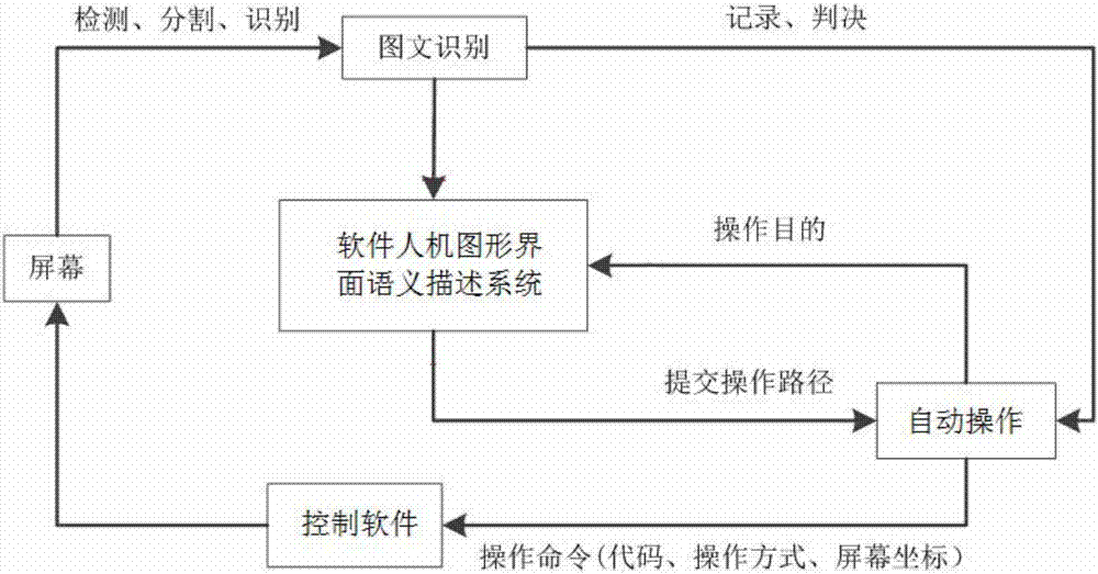
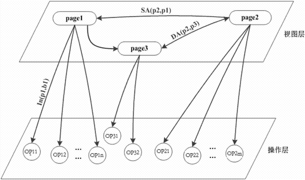
[0055] Embodiment 2: This embodiment provides a graphical interface semantic description system, which includes a view module (view layer) and an operation module (operation layer); wherein,

[0056] The view module includes image information of all interfaces in the object to be operated (software to be analyzed) and identification information that can trigger operations in each interface. In some embodiments, the view module can also include other information that does not trigger operations in each interface , such as picture information, text information, color information, etc., which are only used for display or other functions; and the operation module includes information about all executable operations in the object to be operated; the executable operation information and the identification that triggers the operation one by one Correspondingly, each executable operation is also grouped according to the interface where the identifier that triggers the operation is loca...

Embodiment 3

[0071] Embodiment 3: This embodiment provides a method for applying the system provided in Embodiment 2 to generate an automatic operation path, the steps of which include:

[0072] S210: Receive the target control command, and determine the target interface according to the target control command; for example, the target control command can be to send a specific command to the mechanical equipment controlled by the software system; when the target control command is determined, it can be described from the graphical interface semantically The specific instruction is searched in the operation module in , and then the interface that triggers the specific instruction in the view module is found; this interface is the target interface.

[0073] S220: Recognize the current interface based on the image; there may be one or more current interfaces; through image collection, and comparing the collected image with the information of each interface pre-stored in the view module, to obta...


PUM


Abstract

The invention relates to the field of intelligent control and in particular relates to a graphical interface semantic description system, a method for building the graphical interface semantic description system and an operation path generating method. According to the invention, a system describing software architecture by using a two-layer relation model is provided; the system describes software systems by using scene semantics more suitable software graphical interfaces of a window style. Compared with the mode that a conventional single semantic network model describes the relations between entity elements in scenes in the same layer by using different relation words (such as inclusion relation, and belonging relation), the double-layer architecture provided by the invention can conveniently determine and infer the relations between the types of entities and entities included in scenes.

Description

technical field [0001] The invention relates to the field of intelligent control, in particular to a graphical interface semantic description system and its establishment method and operation path generation method. Background technique [0002] In the field of combining information technology and industrial automation, the realization of automated production and testing with artificial intelligence is one of the hotspots in recent years. It is a development trend to replace manual intelligent automation control with intelligent mechanized operations; in addition, some comprehensive Strong and complex products, such as airplanes, automobiles, ships, etc., require a large number of functional simulations, performance tests, and result analysis before they are put into use. Industrial robots are widely used in automated production and testing processes. They can not only It is of great significance to reduce labor intensity, increase labor productivity, reduce labor cost, and ...

Claims


Application Information

Patent Timeline
Patent Type & Authority Applications(China)
IPC IPC(8): G06F9/44
Inventor 伍瑞卿刘健余大彦李小翠陈伟顾庆水
Owner UNIV OF ELECTRONICS SCI & TECH OF CHINA
Learn More