
Method and device for manufacturing an array line laser quantum dot backlight module

A technology of backlight module and line laser, which is applied in the direction of lighting devices, nonlinear optics, components of lighting devices, etc., to achieve the effect of reducing the width

Active Publication Date: 2019-06-14
NANJING 55TH INSTION TECH DEV
View PDF8 Cites 0 Cited by
  • Summary
  • Abstract
  • Description
  • Claims
  • Application Information

AI Technical Summary

Problems solved by technology

[0006] At present, researchers are engaged in the research and development of backlight light source based on quantum dots. However, the excitation light source is blue LED. Since LED is a broad-spectrum light source, the spectrum of the light source is very wide, and the advantages of quantum dots cannot be well utilized. Therefore, there is an urgent need for An excitation light source with a purer color, so that the broad-spectrum color gamut formed by quantum dots is wider and the color is more pure

Method used


Image

  • Method and device for manufacturing an array line laser quantum dot backlight module
  • Method and device for manufacturing an array line laser quantum dot backlight module
  • Method and device for manufacturing an array line laser quantum dot backlight module

Examples


Embodiment Construction

[0039] The present invention is described below in conjunction with accompanying drawing:

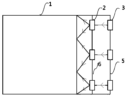
[0040] figure 1 It is an overall structure of an array line laser quantum dot light emitting device and a backlight module. It includes the blue laser light source 3 on the right, and the inner side of the laser light source is an arrayed prism group, that is, an arrayed Powell prism group 2, a light guide plate 105, a quantum dot film group, and subsequent optical coupling components.

[0041] Among them, the blue laser light source is composed of semiconductor lasers. In order to reduce the temperature increase that may be caused by long-term exposure, the blue laser light source is equipped with a special heat dissipation structure, which consists of ordinary air heat sink guide grooves along the end of the laser module from left to right, which are not shown in the figure out.

[0042] The number of arrayed laser light sources is determined by the size of the light guide plate 10...


PUM

PropertyMeasurementUnit
wavelengthaaaaaaaaaa
poweraaaaaaaaaa

Abstract

The present invention relates to an array line laser quantum dot backlight module set fabrication method and device. The device comprises at least one excitation point light source and a flat plate type light guide plate, wherein the excitation point light sources are blue laser light sources which are distributed in an arrayed manner; the device further comprises line laser forming control elements; the line laser forming control elements are located between the excitation point light sources and the flat plate type light guide plate; the line laser forming control elements are Powell lenses; the Powell lenses are arranged in an arrayed manner; the axial azimuth angles of the Powell lenses are adjusted through lens holders; distances between the Powell lenses and the blue laser light sources are adjustable; and an included angle between the incidence direction of line laser formed by the Powell lenses at the side surface of the light guide plate and the normal of the side surface of the light guide plate is adjusted through the lens holders. With the method and device of the invention adopted, the wavelength of the light sources and the brightness and power consumption of the lasers can be controlled, and therefore, highlighted laser can effectively become line laser, and the line laser can enter the light guide plate.

Description

technical field [0001] The invention relates to the field of laser display and lighting, in particular to a manufacturing method and device for an array line laser quantum dot backlight module. Background technique [0002] With the development of social science and technology, people have higher and higher requirements for the optical performance of displays. From early fluorescent tube backlit displays to current LED backlit displays. At the same time, from computer display, to mobile phone, to large screen, to home theater, all reflect the development of display technology. However, any technology has its limitations. Although LED has become a hot spot in the market today and has been greatly popularized, there are still development bottlenecks in some aspects, especially in terms of brightness, stability and color gamut. Therefore, people are trying to develop new technologies to improve existing products, and the laser as a light source is at the right time. [0003]...

Claims


Application Information

Patent Timeline
Patent Type & Authority Patents(China)
IPC IPC(8): G02B6/00G02F1/13357F21V5/04F21V9/30
CPCF21V5/04G02B6/0066G02F1/133615G02F1/133614
Inventor 张玉平宋文陈亮刘雄
Owner NANJING 55TH INSTION TECH DEV
Learn More