
Water dispenser electric heating device

A heating device, electromechanical technology, applied in water heaters, fluid heaters, lighting and heating equipment, etc., can solve the problems of leakage, large temperature control error of the device, hidden safety hazards, etc., to meet the experience effect and accurate temperature control. Effect

Pending Publication Date: 2017-09-15
厦门骊水科技有限公司
View PDF0 Cites 2 Cited by
  • Summary
  • Abstract
  • Description
  • Claims
  • Application Information

AI Technical Summary

Problems solved by technology

[0003] 1. Heating method: The existing heater adopts a fast heating coil, water and electricity together, which is insufficient in energy saving and heat loss control, especially easy to form scale on the heating coil;
[0004] 2. The cold water connected to the existing heater is directly from the top of the water tank to the bottom of the tank, or directly flushed upward from the bottom of the water tank. The remaining hot water in the water tank is mixed with cold water, all due to the use of heat The reason for fast adding coil;
[0005] 3. The heater heats the water to a boiling state, and the pressure in the water storage tank increases, which is prone to hidden dangers of pressure explosion;
[0006] 4. The reason why the heating tube of the existing heater is placed inside the water tank is that the overheating sensing device installed cannot be reasonably positioned to sense the base point of the overheating temperature, which is easy to misjudge;
[0007] 5. Existing heaters are insufficient in terms of energy saving, heat loss, and consumer experience. For example, a 2.4L water tank only has a boiling water usage rate of less than 1.2 liters after being boiled; The pressure is not good, and there is a risk of bursting; the welding method is argon arc welding, which is easy to corrode and water leakage, and has potential safety hazards; in terms of temperature control methods, the temperature control error of existing product devices is large

Method used


Image

  • Water dispenser electric heating device
  • Water dispenser electric heating device
  • Water dispenser electric heating device

Examples


Embodiment

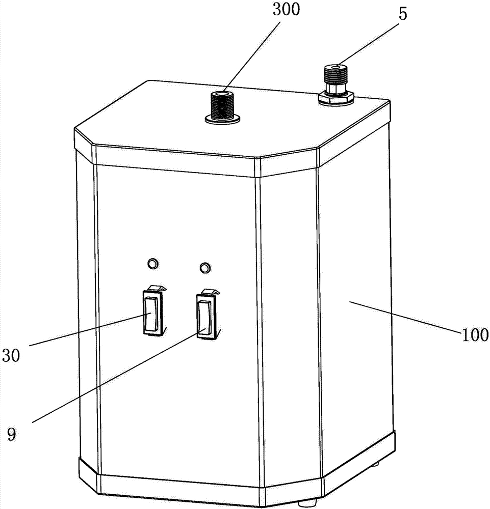
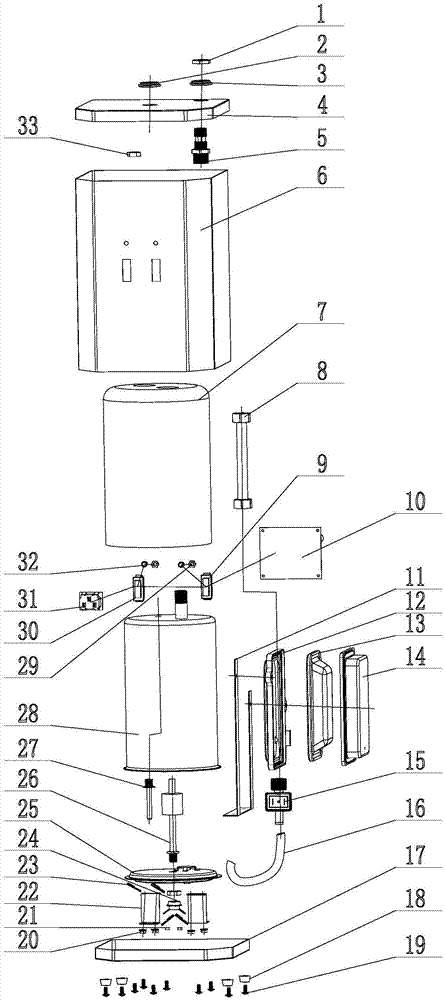
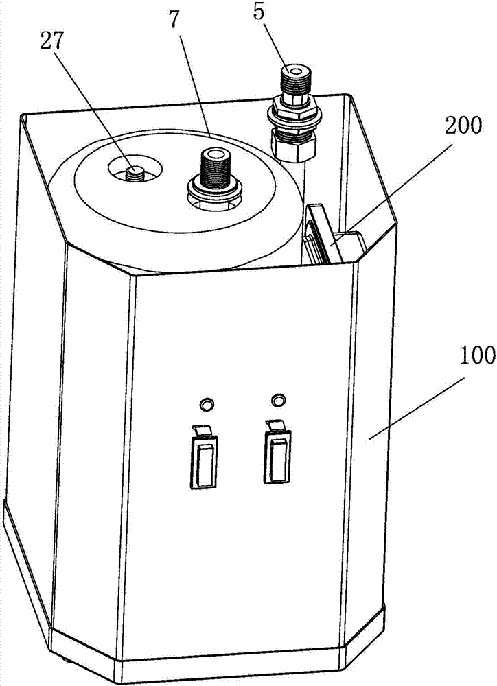
[0030] Example: see Figure 1 to Figure 5 , an electric heating device for a water dispenser, comprising a shell 100, an inner tank 28 and an air storage chamber 200, the inner tank 28 and the air storage room 200 are arranged in the outer shell 100, and the outlet pipe head 300 connected to the inner tank 28 extends outside the outer shell, and enters the The water pipe passes through the shell and connects to the water inlet nozzle 400 at the bottom of the inner tank 28. An air storage chamber 200 is arranged on the water inlet pipeline where the water inlet pipe is located. When the water pipe enters the water, the inner cavity of the air storage chamber 200 shrinks under the negative pressure under the action of the water flow. When the inner container is full, the water inlet pipe is closed, and the air storage chamber sucks the water in the inner container so that the inner container 28 forms a safe space above the water surface for protection. Boiled water overflows due...


PUM


Abstract

The invention discloses an electric heating device for a water dispenser, which comprises a shell, an inner tank and an air storage chamber, the inner tank and the air storage room are arranged in the outer shell, the water outlet pipe head connected to the inner tank extends outside the outer shell, and the water inlet pipe passes through the outer shell and is connected to the At the bottom of the inner tank, there is an air storage chamber on the water inlet pipeline where the water inlet pipe is located. The air storage chamber has a shrinkable inner cavity, and the inner cavity communicates with the water inlet pipeline. The pressure shrinks, the water inlet pipe is closed, and the air storage chamber sucks the water in the inner tank so that the inner tank forms a safe space above the water surface to protect the boiling water from overflowing caused by the heating of the inner tank. The bottom of the inner tank of the present invention is equipped with a cold and hot stratifier, that is, the cold water is arranged from the bottom up to realize the stratified design of cold and hot water. Due to the reasonable effect of the Venturi in the present invention, the water storage tank is not easy to expand and shrink due to heat after heating And there is a hidden danger of explosion pressure, which has the advantages of safety, reliability, good stability, and accurate temperature control.

Description

technical field [0001] The invention discloses an electric heating device for a drinking water machine, which belongs to the technical field of household heating appliances according to the International Patent Classification (IPC), and in particular relates to an instant electric heater, which can instantly heat drinking water for making tea and coffee. Background technique [0002] Ordinary water heaters are generally used for non-drinking purposes in people's lives, such as bathing; there is an electric water heater on the market - Xiaochubao, which is used for washing dishes and vegetables in the kitchen or washing hands in the bathroom. The hot water that people drink needs a heater to heat the cold water, and then flows out through the faucet water valve. The existing drinking water heating products have deficiencies in the overall structure and layout, specifically; [0003] 1. Heating method: The existing heater adopts a fast heating coil, water and electricity toget...

Claims


Application Information

Patent Timeline
IPC IPC(8): F24H1/12F24H9/00F24H9/18F24H9/20
CPCF24H1/121F24H9/0005F24H9/1818F24H9/2028
Inventor 王瑞艺连明山陈安源林文华
Owner 厦门骊水科技有限公司
Learn More