
Vehicle cooperative lane change method based on artificial neural network and system of vehicle cooperative lane change method

An artificial neural network and vehicle technology, which is applied in the field of the artificial neural network-based vehicle cooperative lane changing method and system field, can solve the problems of lack of quantitative analysis ability, traffic accidents, and inability to adapt to the new traffic environment of mixed driving.

Inactive Publication Date: 2017-09-15
DALIAN UNIV OF TECH
View PDF6 Cites 38 Cited by
  • Summary
  • Abstract
  • Description
  • Claims
  • Application Information

AI Technical Summary

Problems solved by technology

[0003] At present, there are many problems in the lane changing method: (1) The traditional method model mainly relies on unmanned driving itself to obtain information to make decisions, lacks cooperation with human driving, does not have human-like behavior capabilities, and cannot adapt to the new traffic environment of mixed driving; (2) The traditional lane changing method pursues "rational" factors such as vehicle safety and driving efficiency. The actual situation is that the behavior of vehicles is also affected by "irrational" factors such as demonstrations and competitions, and these "irrational" factors are more likely to lead to traffic accidents (3) When most researchers analyze the driver's style, they only use survey sampling and classification, qualitative analysis cannot guarantee accuracy, and lack of quantitative analysis capabilities; (4) Some analysis algorithms simply compare the monitoring data with previous samples, lacking Self-learning ability, style analysis needs to accumulate a certain amount of experience and knowledge to have the ability to predict, and the self-learning function is of great significance to prediction

Method used


Image

  • Vehicle cooperative lane change method based on artificial neural network and system of vehicle cooperative lane change method
  • Vehicle cooperative lane change method based on artificial neural network and system of vehicle cooperative lane change method
  • Vehicle cooperative lane change method based on artificial neural network and system of vehicle cooperative lane change method

Examples


Embodiment 1

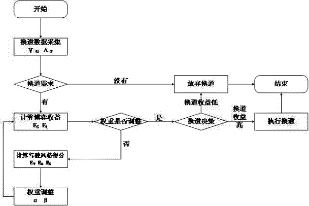
[0221] by figure 1 Take the scenario as an example, the specific steps are as follows:

[0222] S1: Lane change data collection and lane change demand judgment:

[0223] a1. Lane changing data collection: figure 1 medium vehicle V 1 -V 3 During the driving process, the road condition information is collected by the lane change data acquisition module, and the vehicle V 1 The speed is 10m / s, the desired speed is 13.9m / s, and the acceleration is 1.4m / s 2 , 23m away from point b, and the distance from the leading vehicle V 2 16m, distance V 3 4 meters, leading vehicle V 2 The velocity is 14.4m / s and the acceleration is 0.6m / s 2 , lagging the vehicle V 3 The speed is 12.5m / s and the acceleration is 0.9m / s 2 . ;

[0224] a2. Judgment of lane-changing demand: judge whether the vehicle has a lane-changing demand according to the following formula:

[0225]

[0226]

[0227] Among them, Δx i Indicates the current vehicle V 1 with the leading vehicle V 2 Or the r...


PUM


Abstract

The invention discloses a vehicle cooperative lane change method based on an artificial neural network and a system of the vehicle cooperative lane change method. The vehicle cooperative lane change method comprises the following steps of: S1, performing lane change data acquisition and lane change demand judgment; S2, performing game income calculation; S3, performing driving style score calculation; S4, performing weight adjustment; and S5, making a lane change decision. According to the vehicle cooperative lane change method disclosed by the invention, through the quantification of a vehicle driving style, game incomes are adjusted, so that an unmanned automobile can have the behavior ability of human, accidents caused by that the unmanned automobile does not understand a human driving style are avoided, and the traffic efficiency is optimized to the best efforts at a low cost of calculation time under the premise of guaranteeing safety.

Description

technical field [0001] The invention belongs to the technical field of Internet of Vehicles security, in particular to an artificial neural network-based vehicle cooperative lane-changing method and system thereof. Background technique [0002] Traffic accidents are an important issue that endangers human safety and social development. According to statistics, as many as 90% of traffic accidents are caused by human factors such as speeding, drunk driving, fatigue, and improper operation. Therefore, unmanned vehicles have attracted more and more attention from scholars and researchers. ICVs are divided into five levels according to the degree of intelligence: driver assistance, partial autonomous driving, conditional autonomous driving, highly autonomous driving and fully autonomous driving. At this stage, unmanned driving is in the initial stage of development, and the joint driving of people and systems has been realized. There is still a long way to go before fully autom...

Claims


Application Information

Patent Timeline
IPC IPC(8): B60W50/00G06N3/08B60W40/105B60W40/09
CPCB60W40/09B60W40/105B60W50/0097B60W50/0098B60W2050/0025B60W2520/10B60W2554/80B60W2554/801B60W2554/804G06N3/08
Inventor 谭国真薛春铭
Owner DALIAN UNIV OF TECH
Learn More