Cable stripping method

A cable and peeling knife technology, which is applied in the directions of cable installation, cable installation device, and equipment for dismantling/armoring cables, etc., can solve the problems of inconvenience, damage to cable insulation, slow stripping speed, etc. The effect of carrying, increasing speed and safety

Inactive Publication Date: 2017-09-08
STATE GRID HEILONGJIANG ELECTRIC POWER CO LTD HARBIN POWER SUPPLY CO +1
View PDF7 Cites 2 Cited by
  • Summary
  • Abstract
  • Description
  • Claims
  • Application Information

AI Technical Summary

Problems solved by technology

[0004] 1. Use a traditional electrician’s knife to cut the cable sheath. This stripping method is only mastered by experienced masters in more cases, because only they can accurately control the direction of the knife during the cable stripping process. and strength, which requires a lot of practical experience
[0005] 2. Use a spiral cable stripper. This tool is designed to solve the difficult problem of cable stripping. It can effectively adjust the feed rate and cutting angle of the blade to achieve the purpose of cable stripping. However, this cable stripper is expensive. , and it is bulky, heavy, and not easy to carry. Although the peeling effect is good, but because it is a spiral cutting, its peeling speed is relatively slow, and it is relatively more time-consuming
Moreover, its operation steps are cumbersome. It is necessary to adjust the feed rate of the blade while clamping the cable. If the feed rate adjusted by the blade is too small, the cable skin will not be easy to cut off. Injure the inner core of the cable, directly damage the cable insulation, leaving hidden dangers of accidents
Moreover, after a long time, the cutter head needs to be replaced after multiple cuts, but the price is expensive. In addition, considering the amount of engineering itself, if the amount of engineering is small, it is not worth buying a spiral cable stripper

Method used


Image

  • Cable stripping method
  • Cable stripping method

Examples


Embodiment Construction

[0020] The following will clearly and completely describe the technical solutions in the embodiments of the present invention with reference to the accompanying drawings in the embodiments of the present invention. Obviously, the described embodiments are only some, not all, embodiments of the present invention. Based on the embodiments of the present invention, all other embodiments obtained by persons of ordinary skill in the art without creative efforts fall within the protection scope of the present invention.

[0021] It should be noted that, in the case of no conflict, the embodiments of the present invention and the features in the embodiments can be combined with each other.

[0022] The present invention will be further described below in conjunction with the accompanying drawings and specific embodiments, but not as a limitation of the present invention.

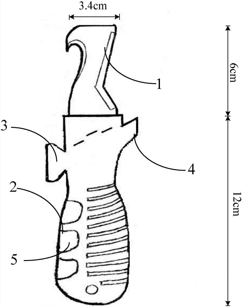
[0023] combine figure 1 Describe this embodiment, this embodiment is a kind of cable stripping method, and this...


PUM


Abstract

The invention provides a safe and effective cable stripping method and specifically relates to a method utilizing a cable stripper for stripping cables. The method is implemented based on the cable stripper including a blade and a handle. The handle is used for fixing the blade. The left side of the blade is a hook-shaped edge and the right side is a Y-shaped edge. The method includes steps of 1, placing a starting position of a to-be-stripped cable on the Y-shaped edge and performing transverse loop cutting at the starting position of the cable by using the Y-shaped edge so as to cut off the sheath of the cable and thus to obtain an annular cut; 2, fixing one end of the cable, holding the handle, hooking the annular cut obtained in step 1 by using the hook-shaped edge of the blade, pressing the handle down so as to adjust a cutting angle, dragging the handle to the other end of the cable and cutting the cable longitudinally to a stripping stop position of the cable; 3, performing annular cutting at the stop position of the cable by using the Y-shaped edge of the blade until the sheath of the cable is removed completely.

Description

technical field [0001] The invention relates to a stripping knife, in particular to a method for peeling cables using the stripping knife. Background technique [0002] The peeling work of power cables has always been difficult, and there has been a lack of special tools, because when the cable is peeled, it cannot be cut smoothly with ordinary knives due to the thick cable sheath. injure staff. [0003] Many cables now use the following methods when stripping: [0004] 1. Use a traditional electrician’s knife to cut the cable sheath. This stripping method is only mastered by experienced masters in more cases, because only they can accurately control the direction of the knife during the cable stripping process. And strength, which requires a lot of practical experience. [0005] 2. Use a spiral cable stripper. This tool is designed to solve the difficult problem of cable stripping. It can effectively adjust the feed rate and cutting angle of the blade to achieve the purp...

Claims


Application Information

Patent Timeline
IPC IPC(8): H02G1/12
CPCH02G1/1231H02G1/1241
Inventor 张一鸣陈铁张滨赵炳程陈玉坤张维袁大为高海涛李正强刘鲁嘉刘文奇张丽岩张春岩
Owner STATE GRID HEILONGJIANG ELECTRIC POWER CO LTD HARBIN POWER SUPPLY CO
Why Eureka
Try Eureka