Safety lowering device

a safety and lowering technology, applied in life-saving devices, building rescue and other directions, can solve problems such as the progress of lowering operations, and achieve the effects of reducing training costs, facilitating multi-functional use, and quick conversion to lowering functions

Active Publication Date: 2015-09-01
BASSETT CARROLL C
View PDF11 Cites 4 Cited by
  • Summary
  • Abstract
  • Description
  • Claims
  • Application Information

AI Technical Summary

Benefits of technology

[0005]A further aspect to this invention is its potential for multifunctional use. Besides its use for the lowering of rescue loads up to about six hundred pounds (600 lbs.), the SLD can easily and almost instantly be converted to function as a simple-to-operate rescue belay device. In the event that the belay function becomes locked-up during use, this device can quickly be converted to the lowering function after remedying the issue that caused the lock-up. This aspect will allow users of two rope systems, for belay and lower, to use one device for both functions simplifying training and reducing the risk of skill retention issues when using different devices.
[0006]In a primary embodiment of this invention, the rope may be pre-rigged by receiving the rescue rope through the device. In this configuration, the rope cannot become detached from the device unless the rope is physically pulled through the device during its use. To eliminate this possibility, stopper knots are tied on the ends of the rope. This is done prior to the rescue event and is known as pre-rigging, a practice that eliminates potential errors in the heat of a rescue as well as accelerating the rigging process dur...

Problems solved by technology

This means that if the user, while using the SLD, becomes incapacitated, the device will automati...

Method used


Image

  • Safety lowering device
  • Safety lowering device
  • Safety lowering device

Examples


Embodiment Construction

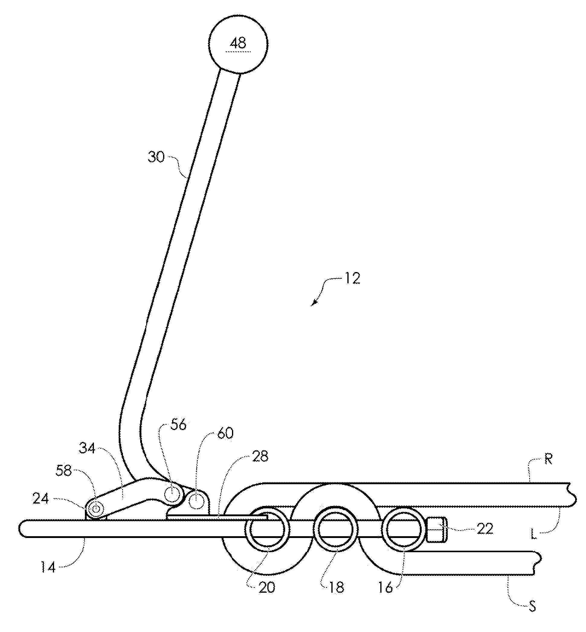
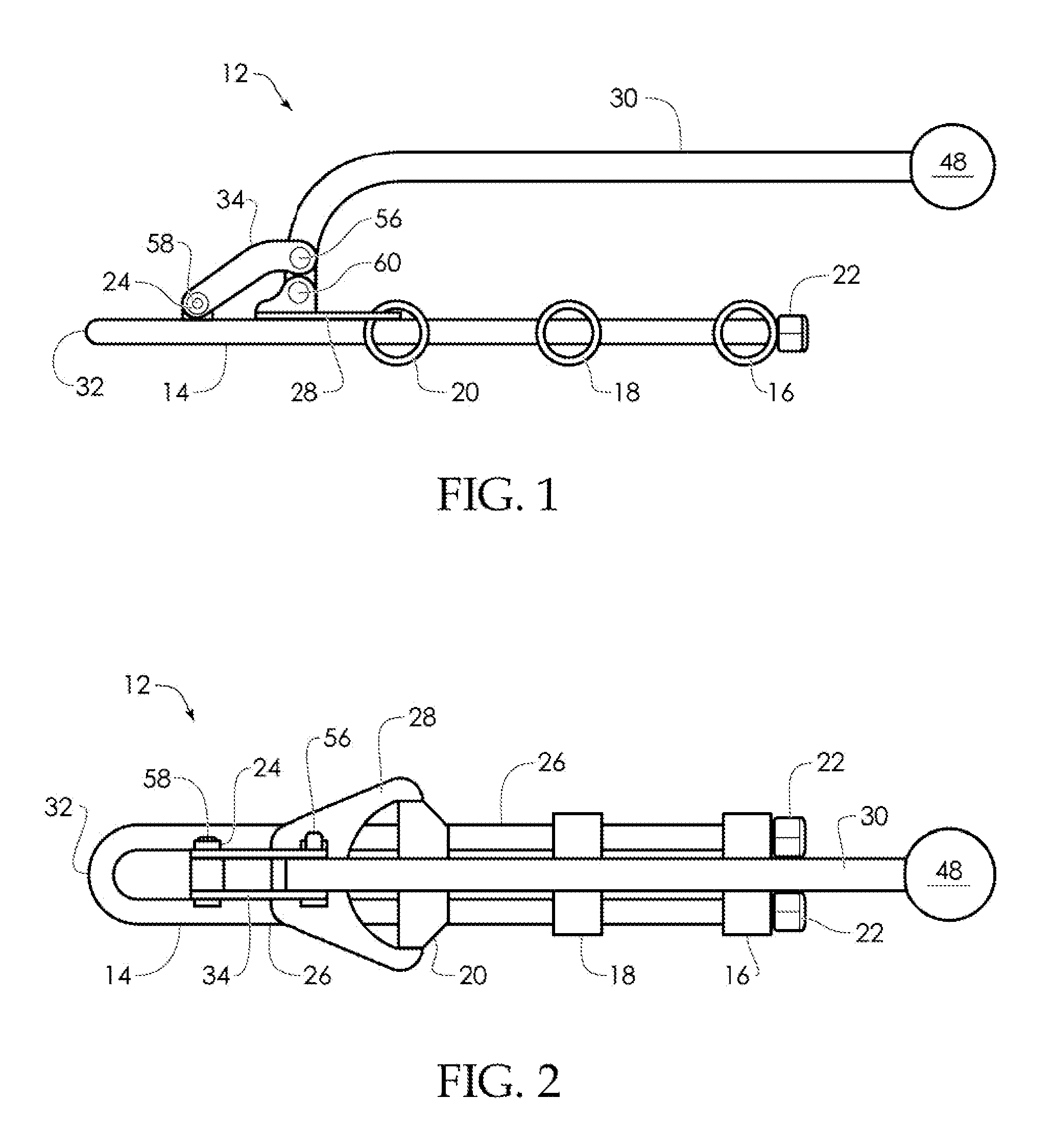
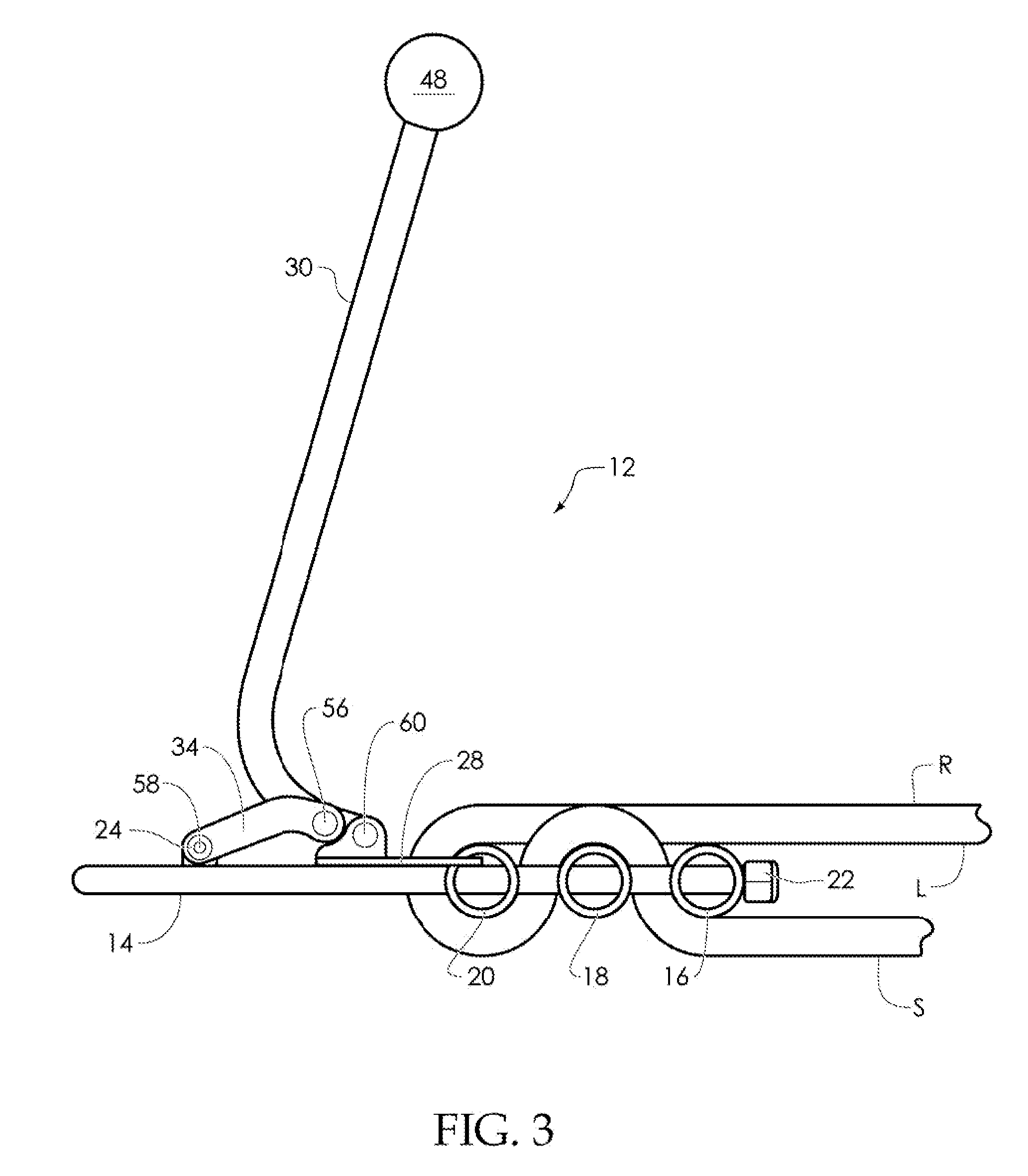
[0025]FIGS. 1 and 2 show the safety lowering device 12 in both side and top views prior to being rigged. The safety device 12 is primarily composed of a U frame 14 upon which is affixed three (3) movable bars 16, 18, and 20 which are free to slide along the U frame 14 and held in place by two (2) abutments 22, e.g. locknuts attached to the ends of the U frame 14. A shoulder retainer 24, e.g., screw, is affixed between parallel arms 26 of the U frame 14 which serves as an anchor point for unloader components. The shoulder retainer 24 may be attached to a block 28 affixed between the arms 26, as shown.

[0026]To use the safety device 12 as an effective rescue belay device the unloader components can be detached by removing the shoulder retainer 24, e.g., screw, and swinging a bar clip 28 off of the third bar 20. Although the present invention is described using a U frame 14, the frame 14 of the present invention may instead be made of components having two parallel arms and a closed end...


PUM


Abstract

A U-shaped frame supporting three bars of circular cross section movable along the arms of the rod, enlarged abutments on the free ends of the rod preventing removal of the bars, and the first bar being attached to a handle so that the bar may be moved up/down the arms by holding/releasing the handle.

Description

RELATED APPLICATIONS[0001]This application claims the benefit of U.S. Provisional Application Ser. No. 61 / 631,249 entitled “SLD (Safety Lowering Device)” filed on 30 Dec. 2011, the contents of which are incorporated herein by reference in its entirety.BACKGROUND OF THE INVENTION[0002]Emergency descent control devices are known. U.S. Pat. No. 6,131,697 teaches a rappelling rope controller which utilizes a U-shaped rod supporting three bars of circular cross section movable along the arms of the rod, and enlarged abutments on the free ends of the rod preventing removal of the bars, but no mechanism for releasing the load are present. US Patent Application No. 2010 / 0236863 teaches an auto-lock compact rope descent device is a bar with holes for guiding a rope used is descent, and a lever designed to pivot or move relative to the bar and compresses the opening of one of the holes. Compressing the opening increases friction and slows or stops descent.[0003]US Patent Application No. 2012 / ...

Claims


Application Information

Patent Timeline
IPC IPC(8): A62B1/04A62B1/14
CPCA62B1/04A62B1/14
Inventor BASSETT, CARROLL C.
Owner BASSETT CARROLL C
Why Eureka
Try Eureka